


11.
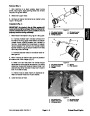
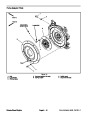
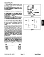
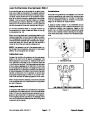
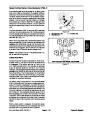
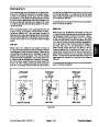
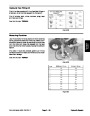
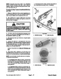
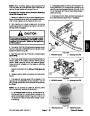
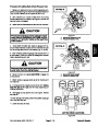
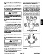
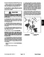
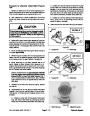
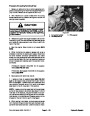
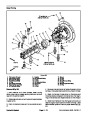
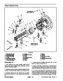
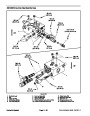
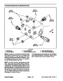
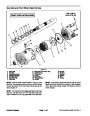
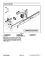
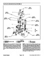
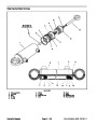
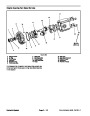
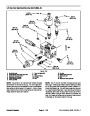
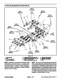
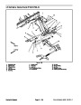
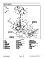
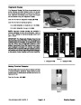
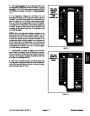
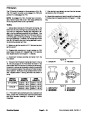
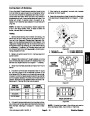
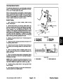
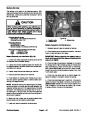
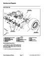
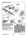
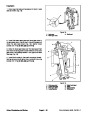
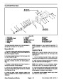
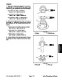
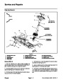
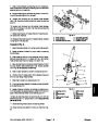
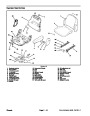
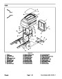
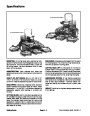
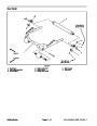
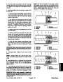
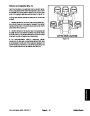
Remove fan motor and fan assembly (Fig. 13).
A. To prevent contamination of hydraulic system,
thoroughly clean exterior of fan motor and fittings.
6
B. Disconnect hydraulic hoses from cooling fan mo-
tor.Putcaps orplugs onfittings andhoses toprevent
contamination. Label hydraulic lines for proper as-
sembly.
3
4
1
5
C. Remove six (6) cap screws and flange nuts that
secure fan motor bracket to radiator.
D. Carefully remove fan motor,fanand motor brack-
et assembly from machine.
2
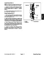
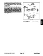
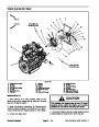
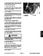
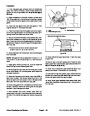
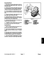
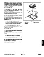
IMPORTANT: The hydraulic pump assembly can re-
main in machine during engine removal. To prevent
pump from shifting or falling, make sure to support
pump assembly before pump mounting fasteners
are removed.
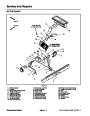
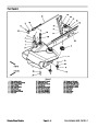
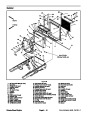
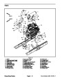
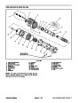
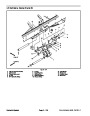
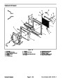
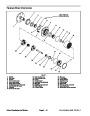
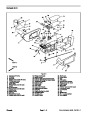
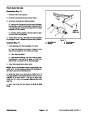
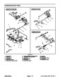
Figure 13
1.
2.
3.
Fan
Fan motor bracket
Fan motor
4.
5.
6.
Cap screw (6 used)
Flange nut (6 used)
Radiator
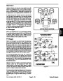
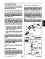
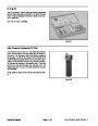
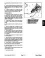
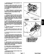
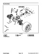
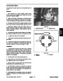
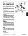
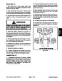
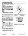
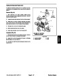
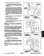
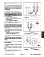
12.Support
hydraulic pump assembly. Remove fasten-
ers that secure pump assembly to engine (see Pump
Assembly Removal in the Service and Repairs section
of Chapter 4 -- Hydraulic System).
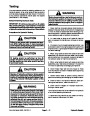
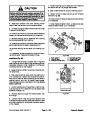
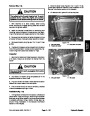
CAUTION
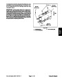
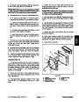
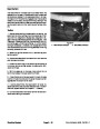
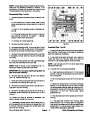
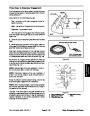
13.Make
sure all cable ties securing the wiring harness,
fuel lines or hydraulic hoses to the engine are removed.
One person should operate lift or hoist while a
second person guides the engine into the ma-
chine.
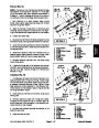
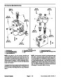
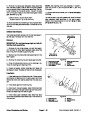
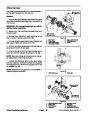
14.Connect
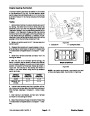
15.Remove
lift or hoist to the lift tabs on engine.
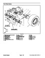
flange nuts, rebound washers and cap
IMPORTANT: Make sure to not damage the engine,
fuel lines, hydraulic lines, electrical harness or oth-
er parts while installing the engine.
screws that secure the engine mounts to the rubber en-
gine supports.
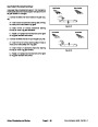
3.
4.
pumpinputshaft.Secureenginetoenginesupportswith
cap screws, rebound washers and flange nuts.
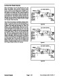
Carefully lower engine into the machine.
CAUTION
Align engine to the engine supports and hydraulic
One person should operate lift or hoist while a
second person guides the engine out of the ma-
chine.
5.
Secure hydraulic pump assembly to engine (see
Pump Assembly Installation in the Service and Repairs
section of Chapter 4 -- Hydraulic System).
IMPORTANT: Make sure to not damage the engine,
fuel lines, hydraulic lines, electrical harness or oth-
er parts while removing the engine.
6.
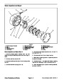
Install fan motor and fan assembly (Fig. 13).
A. Carefullypositionfanmotor,fanandmotorbrack-
et assembly to radiator.
16.Carefully
lift engine from the machine.
17.If
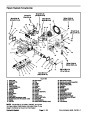
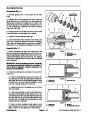
using Figure 10 as a guide.
necessary,remove engine mounts fromtheengine
B. Secure fan motor bracket to radiator with six (6)
cap screws and flange nuts.
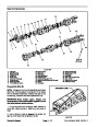
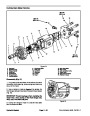
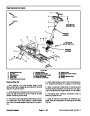
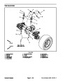
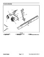
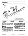
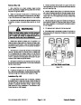
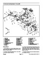
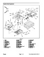
Engine Installation (Fig. 10)
C. Remove caps and plugs placed in hoses and fit-
tings during removal to prevent contamination.
1.
Ifremoved,installengine mounts totheengineusing
Figure 10 as a guide.
D. Connect hydraulic hoses to cooling fan motor
(see Hydraulic Hose and Tube Installation in the
GeneralInformationsectionofChapter4 -- Hydraulic
System).
2.
Connect lift or hoist to the lift tabs on engine.
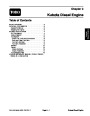
Kubota Diesel Engine
Page 3 -- 14
Groundsmaster 4500--D/4700--D
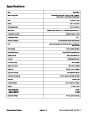
| Categories | Lawn Mower Manual, Sprinkler and Irrigation Manuals, Toro Sprinkler and Irrigation Manuals |
|---|---|
| Tags | Toro Groundsmaster 30857, Toro Groundsmaster 30858, Toro Groundsmaster 4500 D, Toro Groundsmaster 4700 D |
| Download File |
|
| Document Type | Service Manual |
| Language | English |
| Product Brand | Toro. Customer Service Representatives are available by phone:
Monday - Friday 7:30 a.m. to 9:00 p.m. (CDT) - Saturday 8:00 a.m. to 8:00 p.m. (CDT) - Sunday 10:00 a.m. to 8:00 p.m. (CDT)
Canada 1-888-225-4886 USA 1-888-384-9939, Lawn Mower |
| Document File Type | |
| Publisher | toro.com |
| Wikipedia's Page | Toro Company |
| Copyright | Attribution Non-commercial |
(0 votes, average: 0 out of 5)