

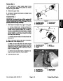


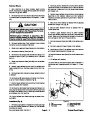
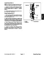


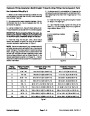
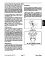


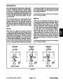

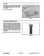


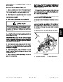


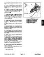
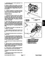

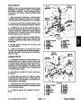

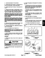

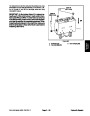


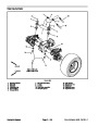
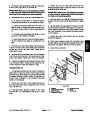

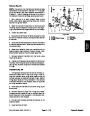

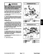


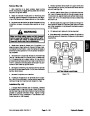
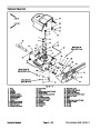

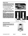
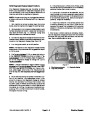
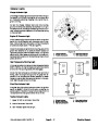
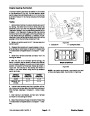


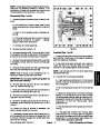


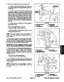
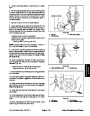
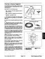

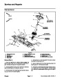


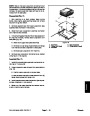


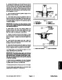
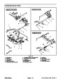


Start Relay
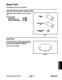
The start relay is located at the power center behind the
operator seat. This relays is attached to the wire har-
ness with a five (5) wire connector (Fig. 37).
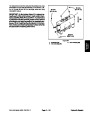
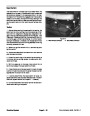
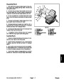
10.Secure relay to mounting bracket and connect wire
harnessconnectortorelay.Installcovertopowercenter.
11.
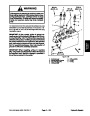
Connect positive (+) cable to battery and then con-
The start relay is used to provide current to the engine
starter motor whenenergized bytheTEC--5002control-
ler. The TEC--5002 controls and monitors the operation
of the start relay.
nect negative (--) cable to battery (see Battery Service
in the Service and Repairs section of this chapter).
3
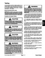
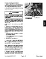
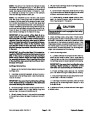
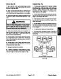
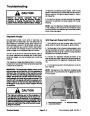
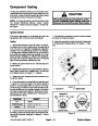
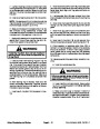
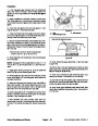
Testing
1
1.
Park machine on a level surface, lower cutting
1
decks, stop engine, engage parking brake and remove
key from the ignition switch.
2
2.
To make sure that machine operation does notoccur
4
unexpectedly, disconnect negative (--) cable from bat-
tery and then disconnect positive (+) cable from battery
(see Battery Service in the Service and Repairs section
of this chapter).
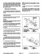
3.
relay.
Remove cover from power center and locate start
5
4.
move relay from mounting bracket for testing.
Disconnect wire harness connector from relay. Re-
6
NOTE: Prior to taking small resistance readings with a
digital multimeter, short the meter test leads together.
The meter will display a small resistance value (usually
5
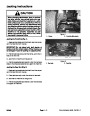
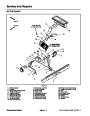
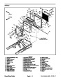
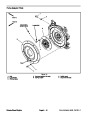
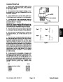
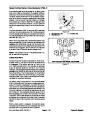
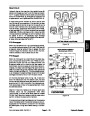
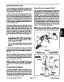
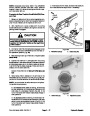
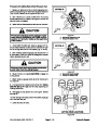
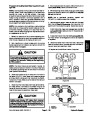
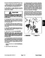
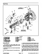
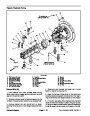
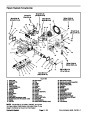
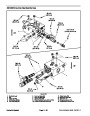
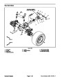
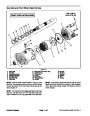
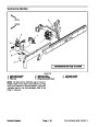
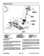
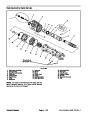
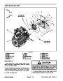
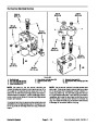
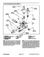
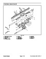
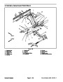
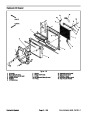
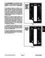
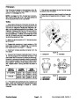
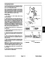
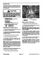
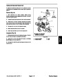
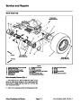
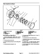
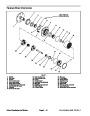
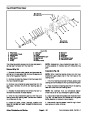
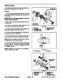
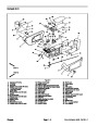
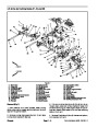
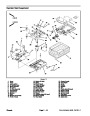
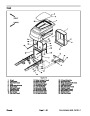
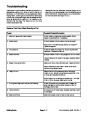
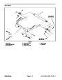
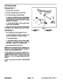
Figure 36
0.5
ohms or less). This resistance is due to the internal
1.
2.
3.
Lock nut
Main power relay
Glow relay
4.
5.
6.
Start relay
Flange head screw
Mounting bracket
resistance of the meter and test leads. Subtract this val-
ue from from the measured value of the component you
are testing.
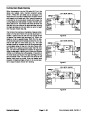
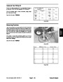
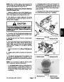
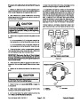
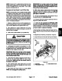
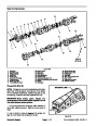
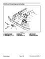
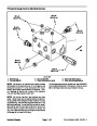
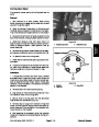
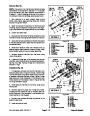
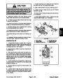
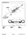
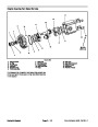
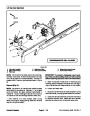
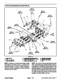
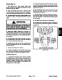
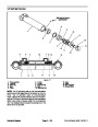
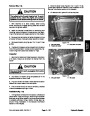
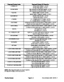
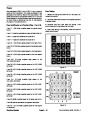
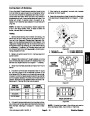
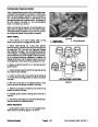
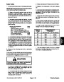
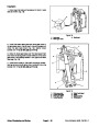
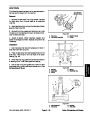
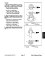
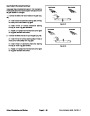
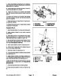
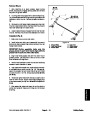
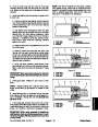
5.
tween terminals 85 and 86 is from 71 to 88 ohms.
Using a multimeter, verify that coil resistance be-
4
3
1
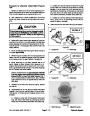
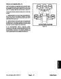
6.
Connectmultimeter (ohmssetting) leadstorelayter-
minals 30 and 87. Ground terminal 86 and apply +12
VDC to terminal 85. The relay should make and break
continuity between terminals 30 and 87 as +12 VDC is
applied and removed from terminal 85.
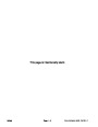
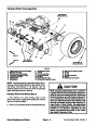
86
85
87A
87
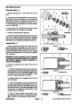
7.
lead from terminal 87.
Disconnect voltage from terminal 85 and multimeter
30
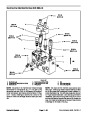
8.
Connectmultimeter (ohmssetting) leadstorelayter-
1
minals 30 and 87A. Apply +12 VDC to terminal 85. The
relay should make and break continuity between termi-
nals 30 and 87A as +12 VDC is applied and removed
from terminal 85.
2
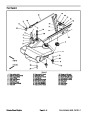
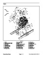
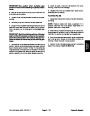
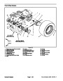
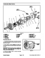
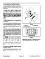
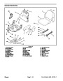
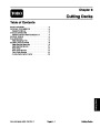
Figure 37
1.
2.
Coil terminal
Common terminal
3.
4.
Normally closed term.
Normally open terminal
9.
Disconnect voltage and multimeter test leads from
the relay terminals.
Groundsmaster 4500--D/4700--D
Page 5 -- 27
Electrical System
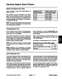
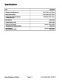
| Categories | Lawn Mower Manual, Sprinkler and Irrigation Manuals, Toro Sprinkler and Irrigation Manuals |
|---|---|
| Tags | Toro Groundsmaster 30857, Toro Groundsmaster 30858, Toro Groundsmaster 4500 D, Toro Groundsmaster 4700 D |
| Download File |
|
| Document Type | Service Manual |
| Language | English |
| Product Brand | Toro. Customer Service Representatives are available by phone:
Monday - Friday 7:30 a.m. to 9:00 p.m. (CDT) - Saturday 8:00 a.m. to 8:00 p.m. (CDT) - Sunday 10:00 a.m. to 8:00 p.m. (CDT)
Canada 1-888-225-4886 USA 1-888-384-9939, Lawn Mower |
| Document File Type | |
| Publisher | toro.com |
| Wikipedia's Page | Toro Company |
| Copyright | Attribution Non-commercial |
(0 votes, average: 0 out of 5)