

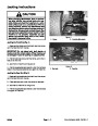


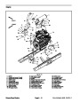


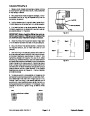
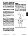


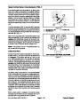

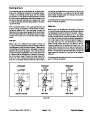


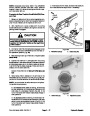
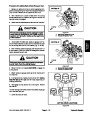
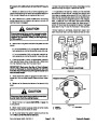
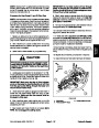
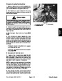


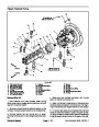

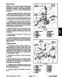
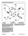

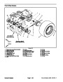
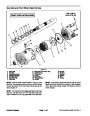
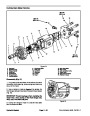

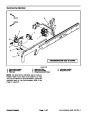
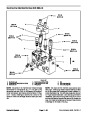

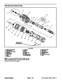

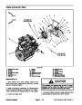


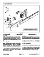
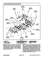


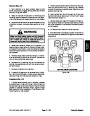
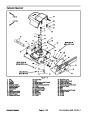


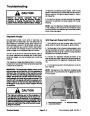
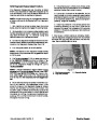
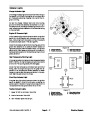
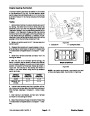


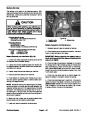
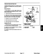

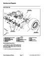
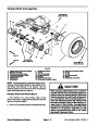
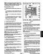


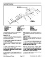
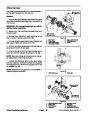
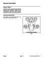

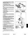


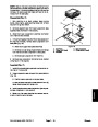


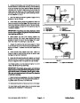
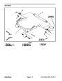


Traction Neutral Switch
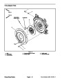
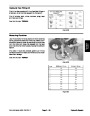
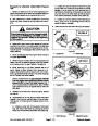
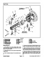
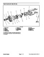
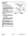
The traction neutral switch is closed when the traction
pedalisintheneutralpositionandopenswhenthepedal
is depressed in either direction. The switch is located on
the right side of the piston (traction) pump (Fig. 46).
See Piston Pump Control Assembly in Chapter 4 -- Hy-
draulic Systems for disassembly and assembly proce-
dures for the neutral switch.
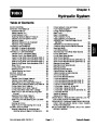
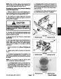
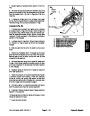
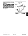
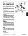
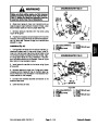
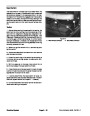
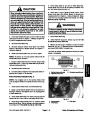
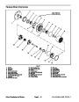
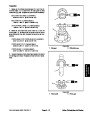
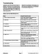
Testing
Before disconnecting the traction neutral switch for test-
ing, the switch and its circuit wiring should be tested as
a TEC input with the Diagnostic Display (see Diagnostic
Display in the Troubleshooting section of this chapter).
If the Diagnostic Display verifies that neutral switch and
circuit wiring are functioning correctly, no further switch
testingisnecessary.If,however,theDisplaydetermines
that neutral switch and circuit wiring are not functioning
correctly, proceed with test.
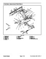
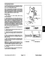
2
1
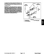
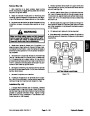
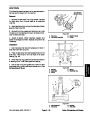
To test the traction neutral switch, make sure that the
ignition switch is in the OFF position and the key is re-
moved from the switch. Disconnect the wire harness
connector from the neutral switch and connect a multi-
meter across the two (2) switch terminals. With the en-
gine turned off, slowly push the traction pedal in a
forwardorreversedirectionwhilewatching themultime-
ter. There should be indications that the traction neutral
switch is opening and closing. Allow the traction pedal
to return to the neutral position. There should be conti-
nuity across the switch terminals when the traction ped-
al is in the neutral position.
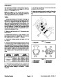
Figure 46
1.
Piston (traction) pump
2. Neutral switch
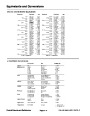
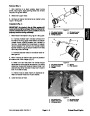
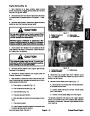
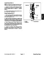
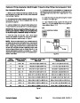
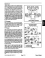
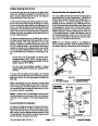
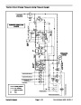
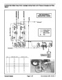
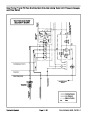
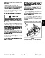
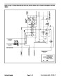
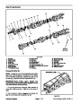
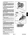
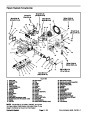
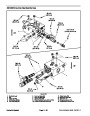
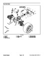
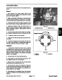
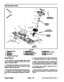
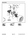
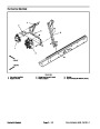
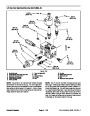
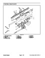
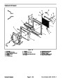
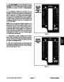
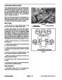
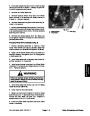
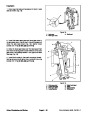
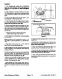
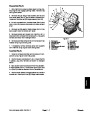
Diode Assembly
The engine wire harness contains a diode that is used
for circuit protection from voltage spikes when the en-
gine starter solenoid is de--energized. The diode plugs
into the wiring harness near the starter motor (see En-
gine Wire Harness Drawing in Chapter 9 -- Foldout
Drawings).
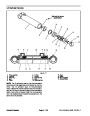
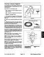
2
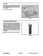
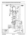
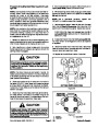
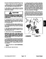
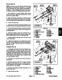
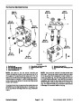
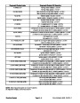
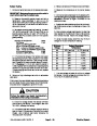
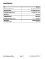
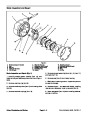
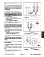
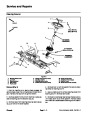
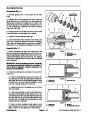
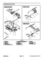
Diode Test
3
1
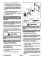
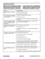
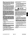
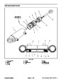
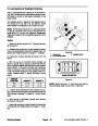
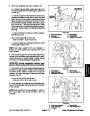
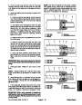
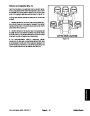
The diode (Fig. 47) can be individually tested using a
digital multimeter (diode test or ohms setting) and the
table to the right.
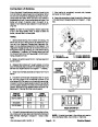
Figure 47
1.
2.
Diode
Male terminal
3.
Female terminal
Multimeter
Red Lead (+)
on Terminal
Multimeter
Black Lead (--)
on Terminal
Continuity
Female
Male
Male
YES
NO
Female
Electrical System
Page 5 -- 32
Groundsmaster 4500--D/4700--D
| Categories | Lawn Mower Manual, Sprinkler and Irrigation Manuals, Toro Sprinkler and Irrigation Manuals |
|---|---|
| Tags | Toro Groundsmaster 30857, Toro Groundsmaster 30858, Toro Groundsmaster 4500 D, Toro Groundsmaster 4700 D |
| Download File |
|
| Document Type | Service Manual |
| Language | English |
| Product Brand | Toro. Customer Service Representatives are available by phone:
Monday - Friday 7:30 a.m. to 9:00 p.m. (CDT) - Saturday 8:00 a.m. to 8:00 p.m. (CDT) - Sunday 10:00 a.m. to 8:00 p.m. (CDT)
Canada 1-888-225-4886 USA 1-888-384-9939, Lawn Mower |
| Document File Type | |
| Publisher | toro.com |
| Wikipedia's Page | Toro Company |
| Copyright | Attribution Non-commercial |
(0 votes, average: 0 out of 5)