
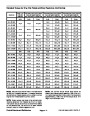


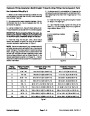


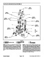


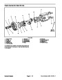


Procedure for Lift/Lower Circuit Relief Pressure
Test
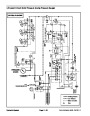
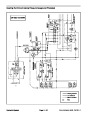
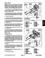
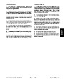
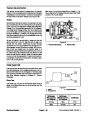
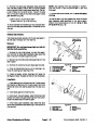
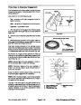
B. If pressure is too low, check for restriction in gear
pump intake line. Check the lift cylinders for internal
leakage. If pump intake line is not restricted and lift
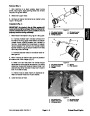
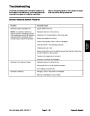
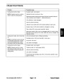
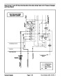
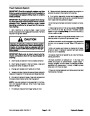
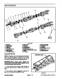
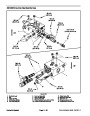
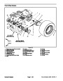
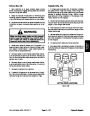
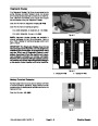
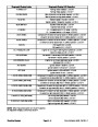
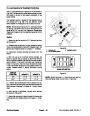
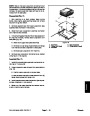
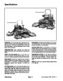
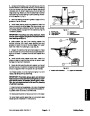
cylinders are not leaking, remove cap on relief valve
(Fig. 52). Adjust the relief valve by rotating adjust-
ment socket clockwise (increase relief pressure).
1.
Make sure hydraulic oil is at normal operating tem-
peraturebyoperatingthemachineforapproximatelyten
minutes. Make sure the hydraulic tank is full.
(10)
2.
decks fully raised. Apply the parking brake and stop en-
gine.
Park machine on a level surface with the cutting
C. If pressure is still too low after relief valve adjust-
ment, pump P4 or lift cylinder(s) should be sus-
pected of wear or damage.
9.
Lower and secure hood after testing is completed.
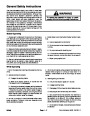
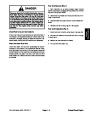
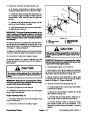
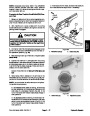
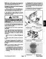
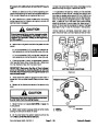
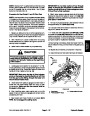
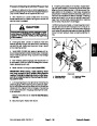
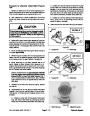
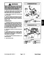
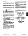
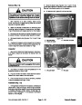
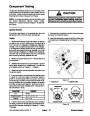
CAUTION
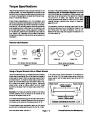
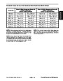
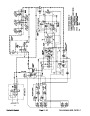
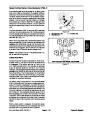
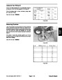
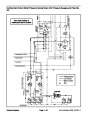
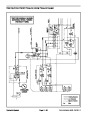
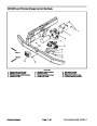
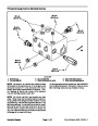
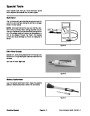
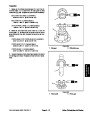
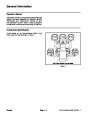
FRONT
GM 4500--D
Prevent personal injury and/or damage to equip-
ment. Read all WARNINGS, CAUTIONS and Pre-
cautions for Hydraulic Testing at the beginning
of this section.
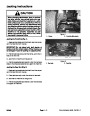
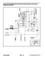
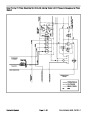
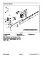
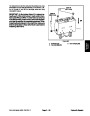
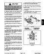
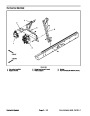
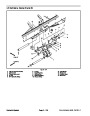
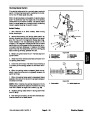
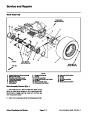
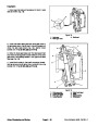
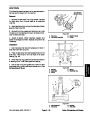
3.
Raise and support hood to gain access to lift control
2
manifold (Fig. 50 or 51). Connect a 5000 PSI (350 bar)
pressure gaugewith hydraulic hose attached to liftman-
ifold test port G1. Route gauge hose to allow hood to be
safely lowered.
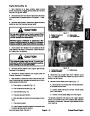
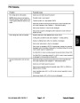
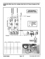
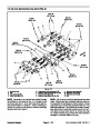
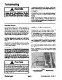
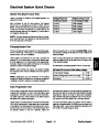
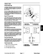
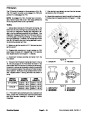
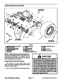
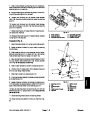
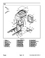
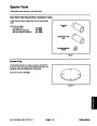
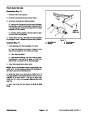
1
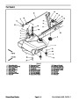
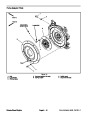
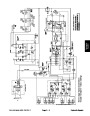
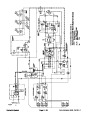
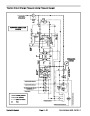
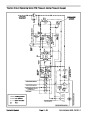
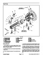
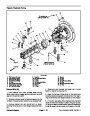
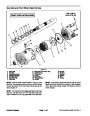
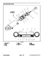
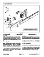
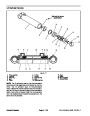
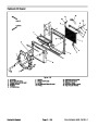
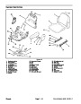
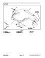
Figure 50
1.
Test port G1
2.
Relief valve
4.
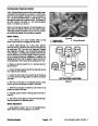
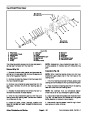
Sit on the seat and start the engine. Move throttle to
full speed (2870 RPM).
5.
raised, monitor the pressure gauge to identify lift/lower
circuit pressure with no load. Record this pressure.
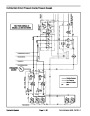
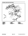
While sitting on the seat, with the cutting decks fully
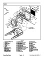
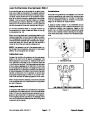
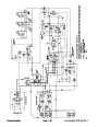
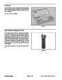
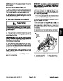
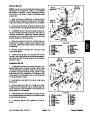
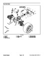
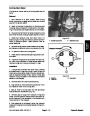
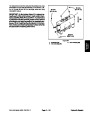
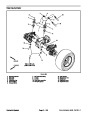
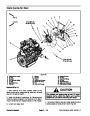
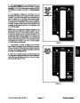
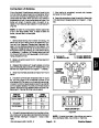
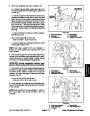
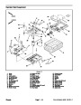
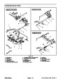
GM 4700--D
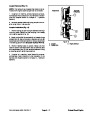
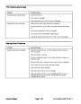
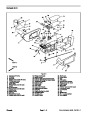
1
6.
While remaining on the seat, depress rear of lift
switch (raise) to allow lift/lower circuit pressure to in-
crease. Momentarily hold the switch with the lift cylin-
ders fully retracted while looking at the pressure gauge
as the lift/lower relief valve opens.
FRONT
2
GAUGE READING TOBEapproximately 1600 PSI
(179
bar) higher than measured lift/lower circuit
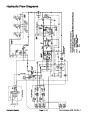
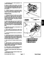
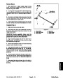
Figure 51
pressure with no load from step 5 above (e.g. if
circuit no load pressure is 300 PSI (21 bar), lift/lower
relief pressure should be approximately 1900 PSI
1.
Test port G1
2.
Relief valve
(200
bar))
7.
Release the lift switch and stop the engine. Record
test results.
2
8.
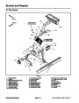
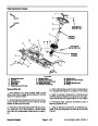
If specification is not met, adjust or clean relief valve
located in the lift control manifold (see Lift Control Man-
ifold Service in the Service and Repairs section of this
chapter).
1
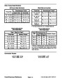
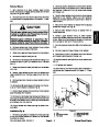
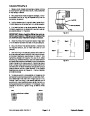
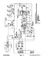
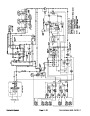
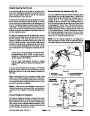
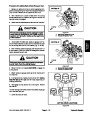
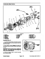
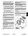
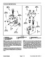
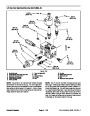
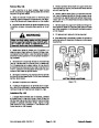
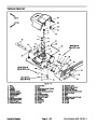
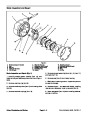
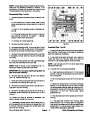
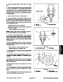
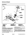
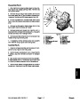
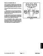
A. If pressure is too high, remove cap on relief valve
(Fig. 52). Adjust relief valve by rotating adjustment
socket counterclockwise (decrease relief pressure).
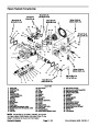
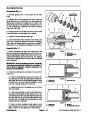
Figure 52
1.
Relief valve cap
2.
Adjustment socket
Groundsmaster 4500--D/4700--D
Page 4 -- 61
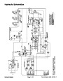
Hydraulic System
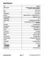
| Categories | Lawn Mower Manual, Sprinkler and Irrigation Manuals, Toro Sprinkler and Irrigation Manuals |
|---|---|
| Tags | Toro Groundsmaster 30857, Toro Groundsmaster 30858, Toro Groundsmaster 4500 D, Toro Groundsmaster 4700 D |
| Download File |
|
| Document Type | Service Manual |
| Language | English |
| Product Brand | Toro. Customer Service Representatives are available by phone:
Monday - Friday 7:30 a.m. to 9:00 p.m. (CDT) - Saturday 8:00 a.m. to 8:00 p.m. (CDT) - Sunday 10:00 a.m. to 8:00 p.m. (CDT)
Canada 1-888-225-4886 USA 1-888-384-9939, Lawn Mower |
| Document File Type | |
| Publisher | toro.com |
| Wikipedia's Page | Toro Company |
| Copyright | Attribution Non-commercial |
(0 votes, average: 0 out of 5)