


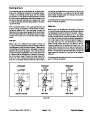


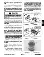


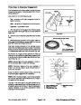


7.
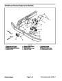
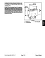
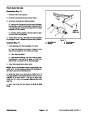
and secure with four (4) flange head screws.
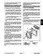
Position steering column brace (item 12) to machine
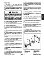
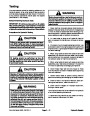
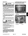
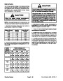
CAUTION
8.
9.
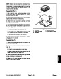
Slide rubber bellows to bottom of steering column.
Position shroud in place and secure with removed
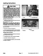
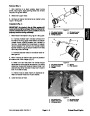
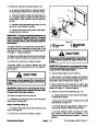
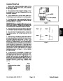
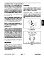
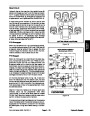
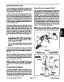
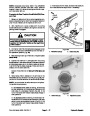
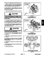
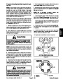
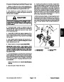
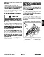
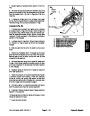
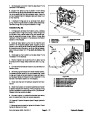
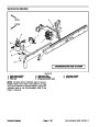
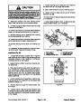
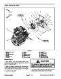
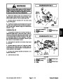
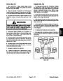
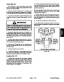
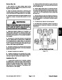
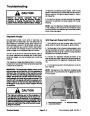
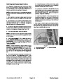
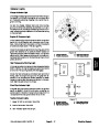
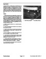
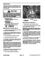
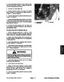
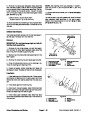
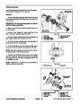
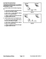
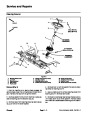
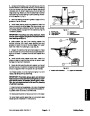
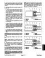
Before opening hydraulic system, operate all hy-
draulic controls to relieve system pressure and
avoid injury from pressurized hydraulic oil. See
Relieving Hydraulic System Pressure in the Gen-
eral Information section of this chapter.
fasteners (Fig. 86).
10.Check
oil if necessary.
oil level in hydraulic reservoir and add correct
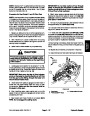
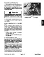
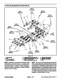
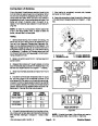
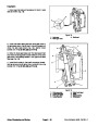
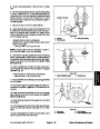
8.
valve. Allow lines to drain into a suitable container.
Disconnect hydraulic lines from steering control
11.
Hydraulic System Start--up in this section).
Follow Hydraulic System Start--up procedures (see
9.
Put caps or plugs on disconnected lines and fittings
to prevent contamination.
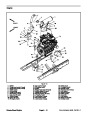
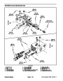
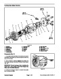
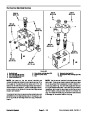
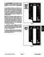
1
2
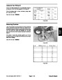
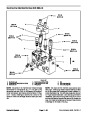
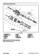
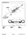
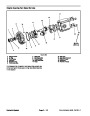
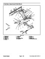
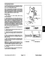
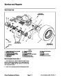
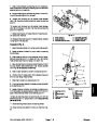
10.Loosen
andremove four (4)socket head screws and
flange nuts that secure steering column to machine.
4
11.
control valve attached from machine.
Remove steering column assembly with steering
3
12.Loosen
andremove four (4) socket head screws that
4
secure steering control valve to steering column.
13.Remove
umn.
steering control valve from steering col-
5
6
14.If
necessary,remove fittings and O--rings from steer-
ing control valve. Discard all removed O--rings.
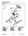
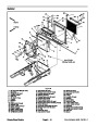
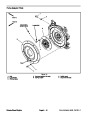
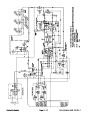
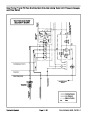
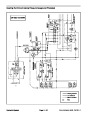
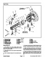
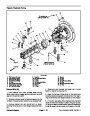
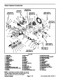
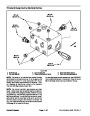
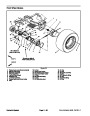
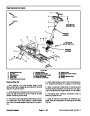
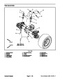
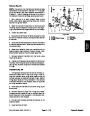
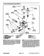
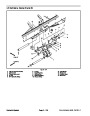
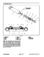
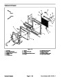
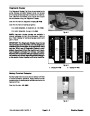
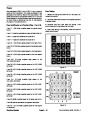
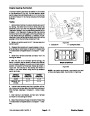
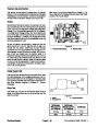
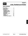
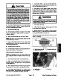
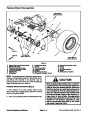
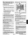
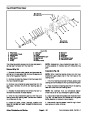
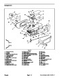
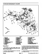
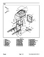
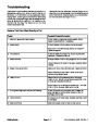
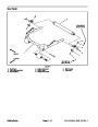
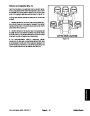
Figure 86
1.
2.
3.
Roller support
4.
5.
6.
Headlight assembly
Flange nut (2 used)
Platform shroud
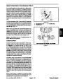
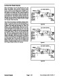
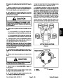
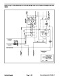
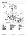
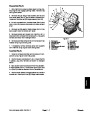
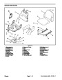
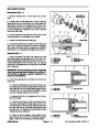
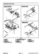
Installation (Fig. 85)
Screw (2 used)
Carriage screw (2 used)
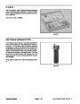
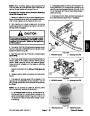
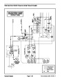
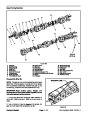
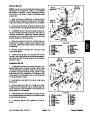
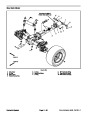
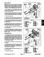
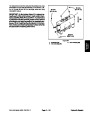
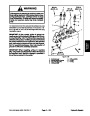
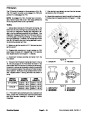
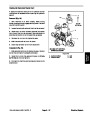
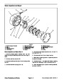
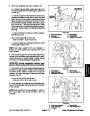
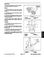
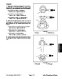
1.
If fittings were removed, lubricate new O--rings with
clean hydraulic oil and install fittings to steering control
valve (see Hydraulic Fitting Installation in the General
Information section of this chapter).
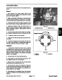
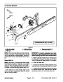
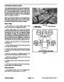
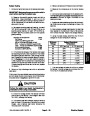
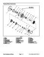
T
2.
Apply antiseize lubricant to splines of steering con-
trol valve shaft.
L
P
R
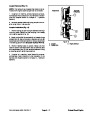
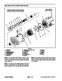
3.
Slide steering control valve shaft into steering col-
umn universal joint. Position control valve with ports to-
ward front of machine. Secure steering control valve to
steering column with four (4) socket head screws.
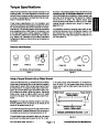
Torquescrewsinacriss--crosspatternfrom7to10ft--lb
E
(9.5
to 13.5 N--m).
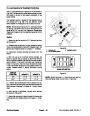
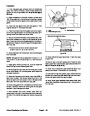
4.
cure steering column in place with four (4) socket head
screws and flange nuts.
Position steering column assembly to machine. Se-
5.
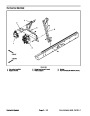
Remove caps and plugs from disconnected lines
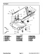
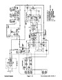
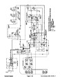
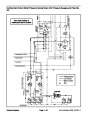
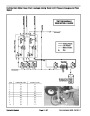
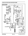
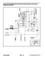
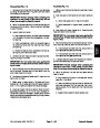
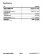
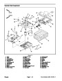
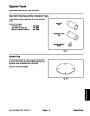
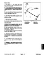
Figure 87
and fittings.
6.
Lubricate new O--rings and connect hydraulic lines
to fittings on steering control valve (see Hydraulic Hose
and Tube Installation in the General Information section
of this chapter).
Groundsmaster 4500--D/4700--D
Page 4 -- 103
Hydraulic System
| Categories | Lawn Mower Manual, Sprinkler and Irrigation Manuals, Toro Sprinkler and Irrigation Manuals |
|---|---|
| Tags | Toro Groundsmaster 30857, Toro Groundsmaster 30858, Toro Groundsmaster 4500 D, Toro Groundsmaster 4700 D |
| Download File |
|
| Document Type | Service Manual |
| Language | English |
| Product Brand | Toro. Customer Service Representatives are available by phone:
Monday - Friday 7:30 a.m. to 9:00 p.m. (CDT) - Saturday 8:00 a.m. to 8:00 p.m. (CDT) - Sunday 10:00 a.m. to 8:00 p.m. (CDT)
Canada 1-888-225-4886 USA 1-888-384-9939, Lawn Mower |
| Document File Type | |
| Publisher | toro.com |
| Wikipedia's Page | Toro Company |
| Copyright | Attribution Non-commercial |
(0 votes, average: 0 out of 5)