


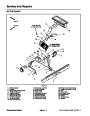


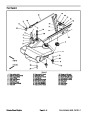
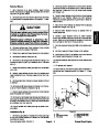
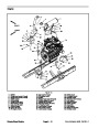
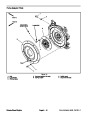


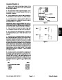
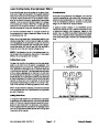


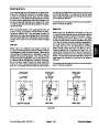

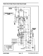


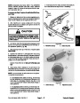
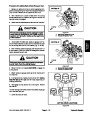
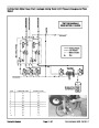
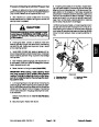
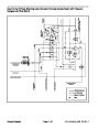


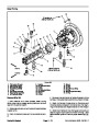
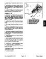
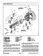
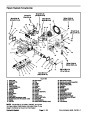

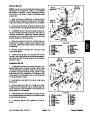
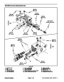

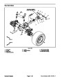
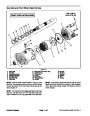
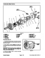

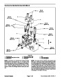

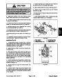
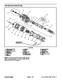

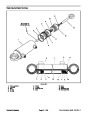
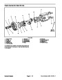

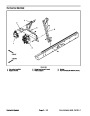

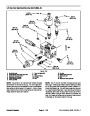


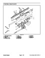
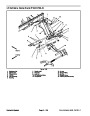
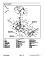


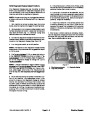
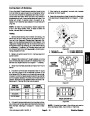
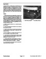


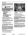


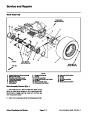
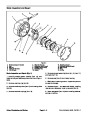

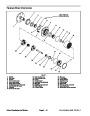


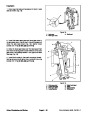
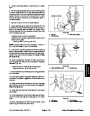
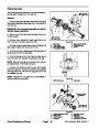
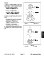


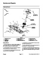
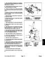
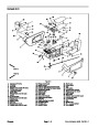


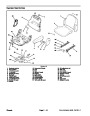

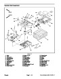
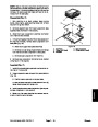


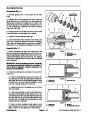
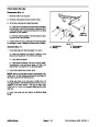


Removal (Fig. 109)
Park machine on a level surface, lower cutting
decks, stop engine, engage parking brake and remove
key from the ignition switch.
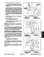
2. Position cylinder barrel clevis to support frame and
insert cylinder pin (item 2) into frame and clevis. Secure
pin with retaining ring.
1.
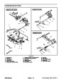
3. Position plastic rollers (item 7) to cylinder shaft cle-
vis. Insert link assembly (item 5) through support frame,
lift links (item 4), plastic rollers and cylinder shaft clevis.
Install rear link to link assembly and secure assembly
with lock nuts.
2.
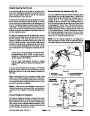
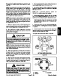
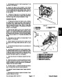
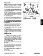
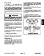
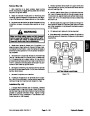
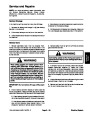
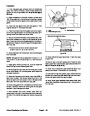
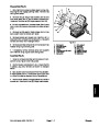
Installing Hydraulic System Components at the begin-
ning of the Service and Repairs section of this chapter.
Read the General Precautions for Removing and
3.
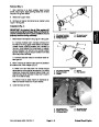
lift cylinder removal, thoroughly clean exterior of lift cyl-
inder.
To prevent contamination of hydraulic system during
4.
Remove caps and plugs from hoses and fittings. At-
tach hydraulic hoses to lift cylinder (see Hydraulic Hose
and Tube Installation in the General Information section
of this chapter).
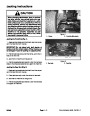
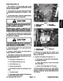
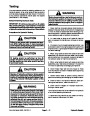
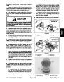
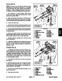
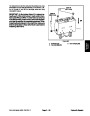
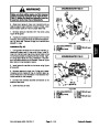
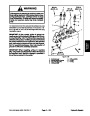
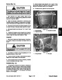
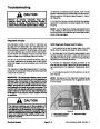
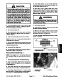
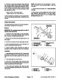
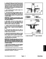
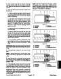
WARNING
5. Fill reservoir with hydraulic fluid as required.
6.
verify that hydraulic hoses and fittings are not contacted
by anything.
After assembly is completed, operate lift cylinder to
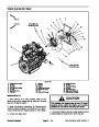
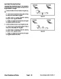
Make sure that cutting decks are fully lowered
before loosening hydraulic lines from lift cylin-
der. If decks are raised as hydraulic lines are
loosened, decks may drop unexpectedly.
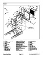
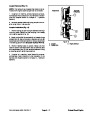
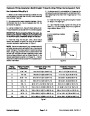
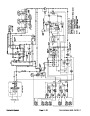
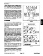
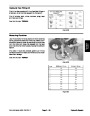
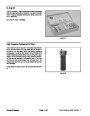
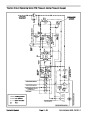
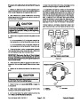
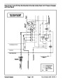
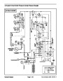
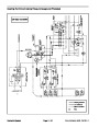
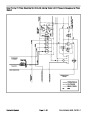
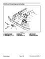
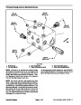
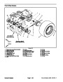
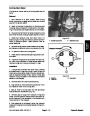
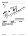
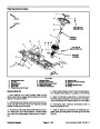
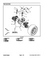
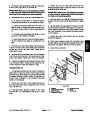
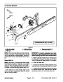
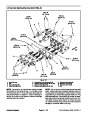
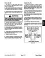
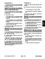
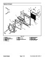
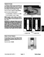
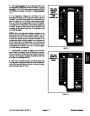
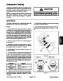
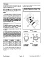
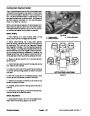
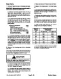
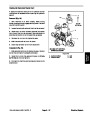
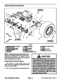
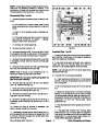
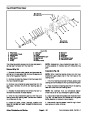
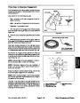
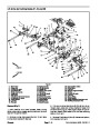
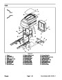
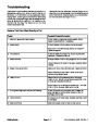
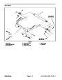
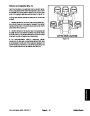
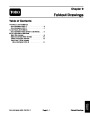
#4
Deck
#1 Deck
#5 Deck
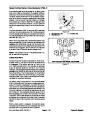
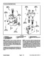
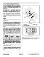
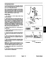
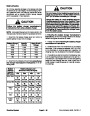
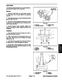
4.
Disconnect hydraulic hoses from lift cylinder. Put
caps or plugs on open hydraulic lines and fittings to pre-
ventsystemcontamination.Labelthehydraulichosesto
show their correct position on the lift cylinder for assem-
bly purposes.
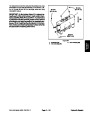
5.
Remove lock nuts (item 9) that secure link assembly
(item 5). Remove rear link (item 8) from link assembly.
Pull link assembly from support frame, lift links (item 4)
and cylinder shaft clevis which will free lift cylinder from
lift arm. Locate and remove plastic rollers (item 7) posi-
tioned on both sides of cylinder clevis.
#
2
#3
Deck
#6 Deck
#7 Deck
(GM4700)
Deck
(GM4700)
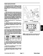
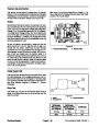
6.
pin (item 2) to thesupport frame.Pullpinfrom frameand
cylinder barrel clevis.
Remove one retaining ring that secures the cylinder
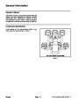
CUTTING DECK LOCATIONS
Figure 110
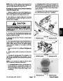
7.
8.
Remove lift cylinder from machine.
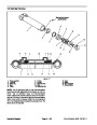
If hydraulic fittings are to be removed from lift cylin-
der, mark fitting orientation to allow correct assembly.
Remove fittings from cylinder and discard O--rings.
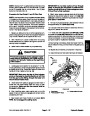
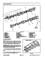
Installation (Fig. 109)
1.
If fittings were removed from lift cylinder, lubricate
and place new O--rings onto fittings. Install fittings into
cylinderopeningsusingmarksmadeduringtheremoval
process to properly orientate fittings. Tighten fittings
(see Hydraulic Fitting Installation in the General Infor-
mation section of this chapter).
Groundsmaster 4500--D/4700--D
Page 4 -- 131
Hydraulic System
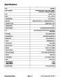
| Categories | Lawn Mower Manual, Sprinkler and Irrigation Manuals, Toro Sprinkler and Irrigation Manuals |
|---|---|
| Tags | Toro Groundsmaster 30857, Toro Groundsmaster 30858, Toro Groundsmaster 4500 D, Toro Groundsmaster 4700 D |
| Download File |
|
| Document Type | Service Manual |
| Language | English |
| Product Brand | Toro. Customer Service Representatives are available by phone:
Monday - Friday 7:30 a.m. to 9:00 p.m. (CDT) - Saturday 8:00 a.m. to 8:00 p.m. (CDT) - Sunday 10:00 a.m. to 8:00 p.m. (CDT)
Canada 1-888-225-4886 USA 1-888-384-9939, Lawn Mower |
| Document File Type | |
| Publisher | toro.com |
| Wikipedia's Page | Toro Company |
| Copyright | Attribution Non-commercial |
(0 votes, average: 0 out of 5)