
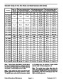
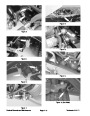


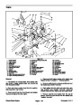
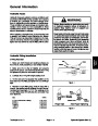


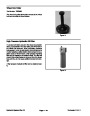


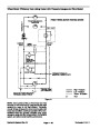
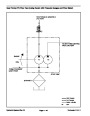


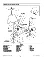
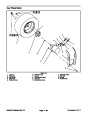
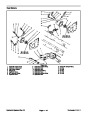
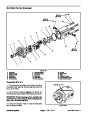


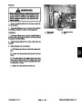
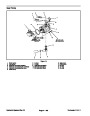


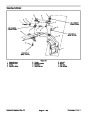
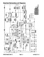

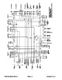
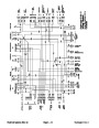
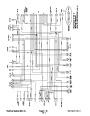


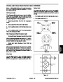
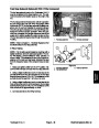

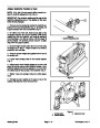
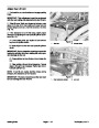
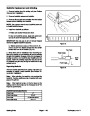


Glow Relay
The glow relay is attached to the radiator assembly.
When energized, the glow relay allows electrical current
to the engine glow plugs.
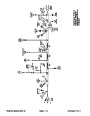
87
86
85
87
30
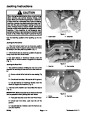
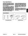
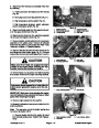
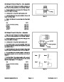
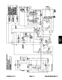
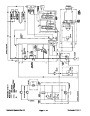
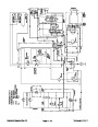
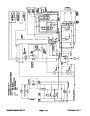
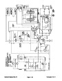
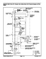
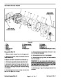
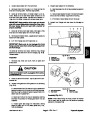
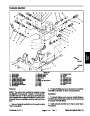
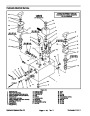
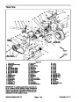
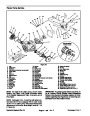
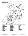
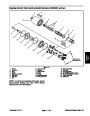
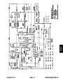
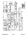
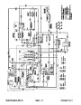
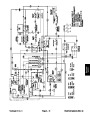
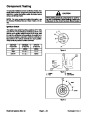
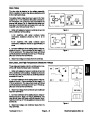
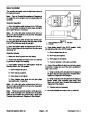
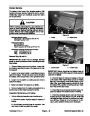
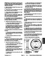
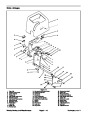
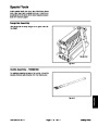
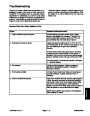
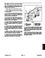
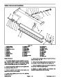
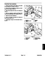
Two styles of glow relays have been used on the Reel-
master 3100−D. On machines with serial numbers be-
low 240000000, two of the four relay connections are
secured with screws (Fig. 6). Machines with serial num-
bers above 240000000 are connected to the wire har-
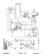
ness with a four wire connector (Fig. 7).
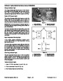
30
85
86
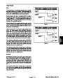
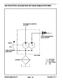
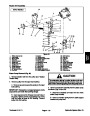
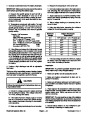
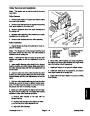
1.
Verify coil resistance between terminals 86 and 85
Figure 6
with a multimeter (ohms setting):
A. On machines with serial numbers below
240000000,
ohms.
resistance should be from 41 to 51
86
87
30
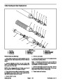
B. On machines with serial numbers above
85
86
240000000,
ohms.
resistance should be approximately 72
85
30
87
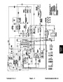
2.
Connect multimeter (ohms setting) leads to relay ter-
minals 30 and 87. Ground terminal 86 and apply +12
VDC to terminal 85. The relay should make and break
continuity between terminals 30 and 87 as 12 VDC is ap-
plied and removed from terminal 85.
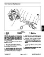
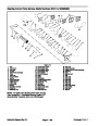
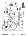
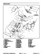
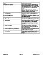
Figure 7
3.
Disconnect voltage and leads from the terminals.
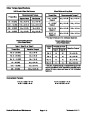
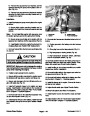
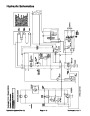
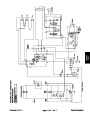
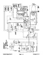
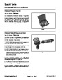
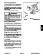
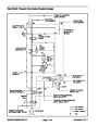
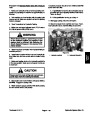
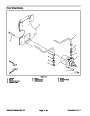
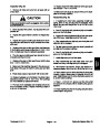
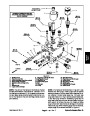
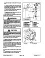
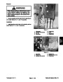
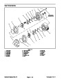
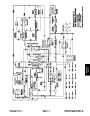
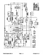
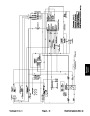
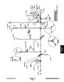
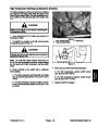
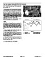
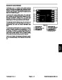
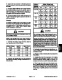
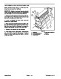
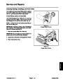
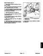
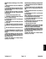
Start, Seat, and High Temperature Shutdown Relays
These relays are located under the control panel on ma-
chines with Serial Numbers below 240000000.
86
87A
87
87
1.
Verify coil resistance between terminals 86 and 85
87A
with a multimeter (ohms setting). Resistance should be
from 80 to 90 ohms. There should be continuity between
terminals 87A and 30.
86
85
30
2.
Connect multimeter (ohms setting) leads to relay ter-
85
30
minals 30 and 87. Ground terminal 86 and apply +12
VDC to terminal 85. The relay should make and break
continuity between terminals 30 and 87 as 12 VDC is ap-
plied and removed from terminal 85.
3.
lead from terminal 87.
Disconnect voltage from terminal 85 and multimeter
TOP VIEW
4.
Connect multimeter (ohms setting) lead to relay ter-
minal 30 and 87A. Apply +12 VDC to terminal 85. The
relay should make and break continuity between termi-
nals 30 and 87A as 12 VDC is applied and removed from
terminal 85.
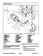
Figure 8
5.
Disconnect voltage and multimeter leads from the
relay terminals.
Reelmaster 3100−D
Page 5 − 31
Electrical Systems (Rev. C)
| Categories | Lawn Mower Manual, Sprinkler and Irrigation Manuals, Toro Sprinkler and Irrigation Manuals |
|---|---|
| Tags | Toro Reelmaster 3100-D |
| Download File |
|
| Document Type | Service Manual |
| Language | English |
| Product Brand | Toro. Customer Service Representatives are available by phone:
Monday - Friday 7:30 a.m. to 9:00 p.m. (CDT) - Saturday 8:00 a.m. to 8:00 p.m. (CDT) - Sunday 10:00 a.m. to 8:00 p.m. (CDT)
Canada 1-888-225-4886 USA 1-888-384-9939, Lawn Mower |
| Document File Type | |
| Publisher | toro.com |
| Wikipedia's Page | Toro Company |
| Copyright | Attribution Non-commercial |
(0 votes, average: 0 out of 5)