


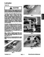


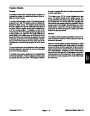
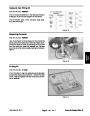


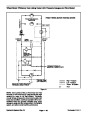


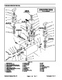
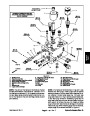


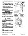


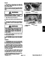


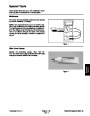


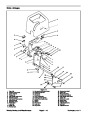
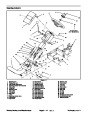

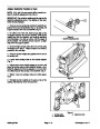
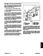
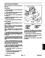


Roller Removal and Installation
Note:
This section can be used for both the front and
rear rollers.
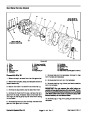
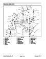
Roller Removal
1.
Remove both height−of−cut pins and hairpin cotters
from each roller bracket.
2
2.
Remove both locknuts from the capscrews securing
each angle bracket to the cutting unit.
1
3.
the cutting unit.
Remove capscrews from both angle brackets and
5
4.
brackets from the cutting unit.
Separate roller assembly, roller brackets, and angle
6
7
4
5.
Remove roller brackets from the roller assembly.
10
3
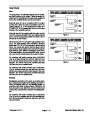
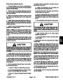
Roller Installation
8
11
9
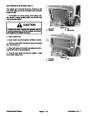
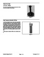
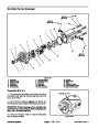
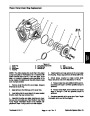
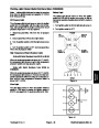
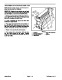
1.
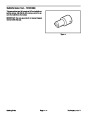
Inspect flanged bushing and bushings for wear; re-
place if necessary.
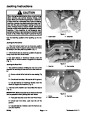
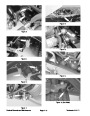
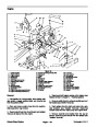
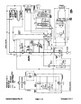
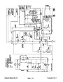
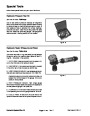
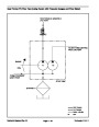
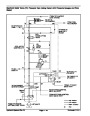
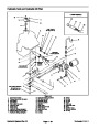
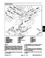
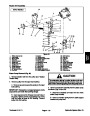
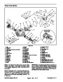
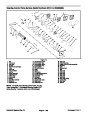
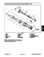
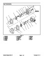
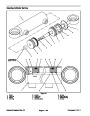
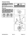
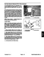
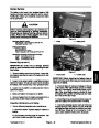
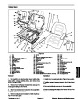
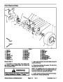
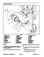
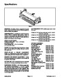
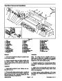
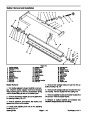
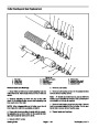
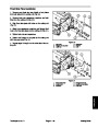
Figure 27
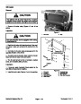
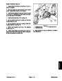
Note:
face inside toward the roller when the roller bracket is
installed onto the cutting unit.
The flanged end of the flanged bushing must
1.
2.
3.
4.
5.
6.
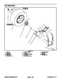
Height−of−cut pin
Hairpin cotter
Roller bracket
Lock nut
Capscrew
Angle bracket
7.
8.
9.
10. Carriage bolt
11. Lock nut
Front roller assembly
Flanged bushing
Bushing
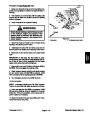
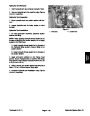
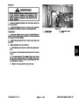
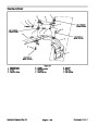
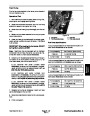
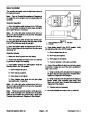
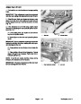
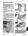
Note:
A soft hammer may be needed to tap the roller
bracket into position on the hex adjustment nut of the
roller.
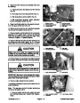
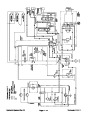
6.
the cutting unit. Secure roller brackets and angle brack-
ets to the cutting unit with capscrews.
Mount roller, roller brackets, and angle brackets to
2.
Insert smaller diameter roller shaft into the flanged
bushing, bushing, and roller bracket. Make sure hex of
the roller bracket mates with the hex adjustment nut
on the roller.
7.
Install both height−of−cut pins and hairpin cotters.
8.
Install both locknuts to the capscrews, and secure
each angle bracket to the cutting unit.
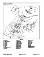
3.
Insert the other end of the roller shaft into the other
bushing and roller bracket. Make sure hex of the roller
bracket mates with the hex adjustment nut on the
roller.
9.
Both Rollers).
Adjust roller level (see Height−of−Cut and Leveling
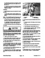
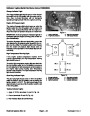
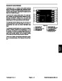
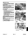
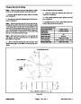
4.
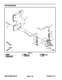
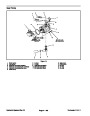
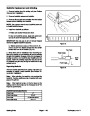
Hold one roller bracket stationary and use the other
bracket as a wrench to loosen or tighten bearing clear-
ance. The roller must not exceed 5 in−lb (0.57 N−m) rol-
ling torque and have no bearing end play.
5.
Make sure roller brackets are aligned prior to instal-
ling them onto the cutting unit. If necessary after bearing
adjustment, align roller brackets as follows:
A. Remove roller bracket on the side with the
flanged bushing.
B. Replace roller bracket so it is aligned to within
+
one hex flat of the roller adjustment nut.
C. Align both roller brackets.
Reelmaster 3100−D
Page 7 − 21
Cutting Units
| Categories | Lawn Mower Manual, Sprinkler and Irrigation Manuals, Toro Sprinkler and Irrigation Manuals |
|---|---|
| Tags | Toro Reelmaster 3100-D |
| Download File |
|
| Document Type | Service Manual |
| Language | English |
| Product Brand | Toro. Customer Service Representatives are available by phone:
Monday - Friday 7:30 a.m. to 9:00 p.m. (CDT) - Saturday 8:00 a.m. to 8:00 p.m. (CDT) - Sunday 10:00 a.m. to 8:00 p.m. (CDT)
Canada 1-888-225-4886 USA 1-888-384-9939, Lawn Mower |
| Document File Type | |
| Publisher | toro.com |
| Wikipedia's Page | Toro Company |
| Copyright | Attribution Non-commercial |
(0 votes, average: 0 out of 5)