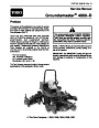


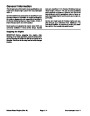
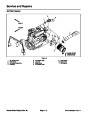
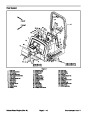


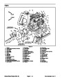
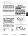


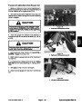
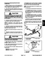
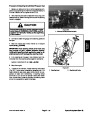
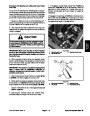


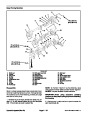

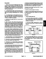

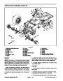
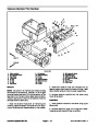
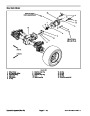
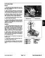
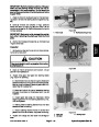
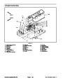


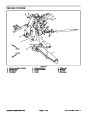

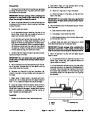
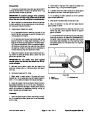
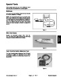
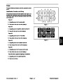

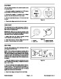
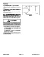
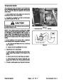
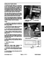


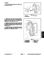
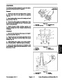
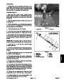
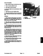

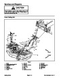


Glow Controller
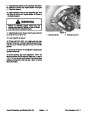
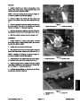
The glow controller is located under the console cover.
2
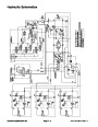
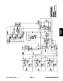
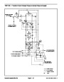
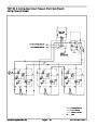
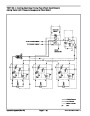
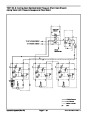
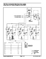
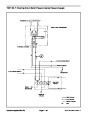
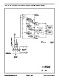
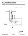
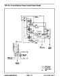
NOTE: Refer to Chapter 9 − Electrical Schematics and
Diagrams when troubleshooting the controller.
3
6
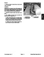
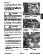
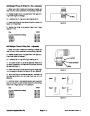
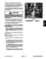
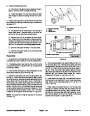
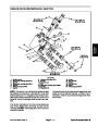
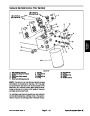
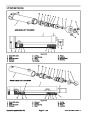
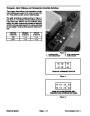
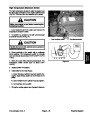
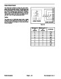
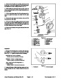
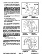
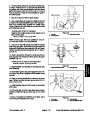
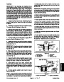
Controller Operation
2
1
5
4
1.
the controller energizes the glow plugs and lights up the
glow lamp for 10 seconds.
When the ignition switch is placed in the ON position,
2.
tion, the glow plugs will energize and the glow lamp will
When the ignition switch is held in the START posi-
1
not light.
3.
When the ignition switch is released from START to
ON, the glow plugs will deenergize and the glow lamp
will remain off.
3
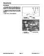
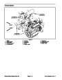
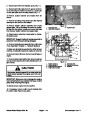
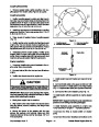
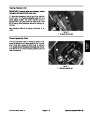
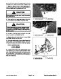
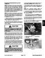
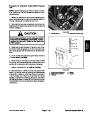
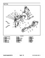
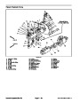
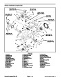
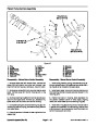
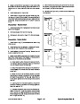
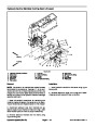
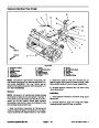
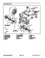
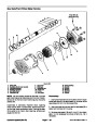
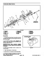
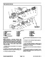
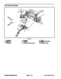
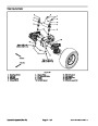
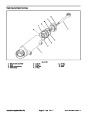
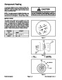
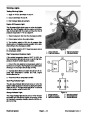
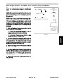
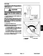
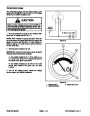
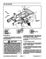
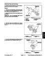
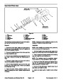
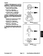
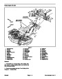
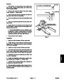
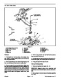
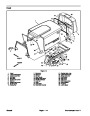
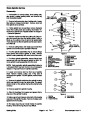
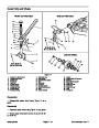
Figure 30
1.
2.
Glow controller end view
Controller top view
3. Controller side view
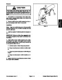
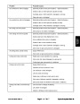
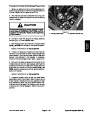
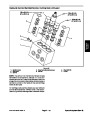
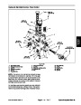
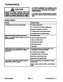
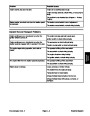
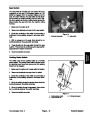
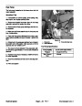
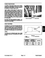
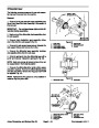
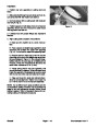
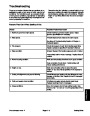
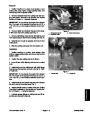
Controller Checks
1.
Make sure there is power from the battery.
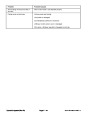
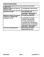
5.
If any of the conditions in step 3 are not met or power
to terminal 1 exists and any of the other conditions in
step 4 are not met:
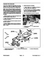
2.
to prevent the engine from starting.
Disconnect electrical connector to the run solenoid
A. Verify continuity of the circuitry from the battery to
the glow relay and glow plugs (see Chapter 9 − Elec-
trical Schematics and Diagrams).
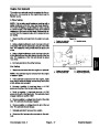
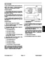
3.
Place ignition switch in the ON position. Verify the fol-
lowing while in the ON position:
A. Glow indicator lamp is on.
B. Glow relay is energized.
C. Glow plugs are energized.
B. Verify continuity of the circuitry from the battery to
ignition switch, glow controller, glow lamp, glow
relay, and ground (see Chapter 9 − Electrical Sche-
matics and Diagrams).
D. Glow indicator lamp goes out and glow plugs
deenergize after 10 seconds.
C. Replace parts as necessary.
6.
Connect electrical connector to the run solenoid.
4.
Place ignition switch in the START position. Verify
the following while in the START position:
A. Glow indicator lamp is out.
B. Glow relay is energized.
C. Glow plugs are energized.
D. Power to terminal 1 of the glow controller.
NOTE: If there is no power to terminal 1 of the glow con-
troller, verify continuity of the circuitry from the ignition
switch to the controller and perform step 4 again (see
Chapter 9 − Electrical Schematics and Diagrams).
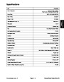
Groundsmaster 4000−D
Page 5 − 21
Electrical System
| Categories | Lawn Mower Manual, Toro Lawn Mower Manual |
|---|---|
| Tags | Toro Groundsmaster 4000 D |
| Download File |
|
| Document Type | Service Manual |
| Language | English |
| Document File Type | |
| Publisher | toro.com |
| Wikipedia's Page | Toro Company |
| Copyright | Attribution Non-commercial |
(0 votes, average: 0 out of 5)