


5.
Determine necessary quantity of support shims.
4
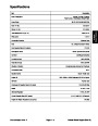
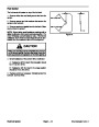
57 to 67 ft−lb
(77 to 91 N−m)
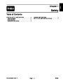
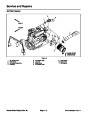
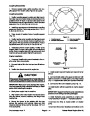
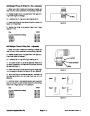
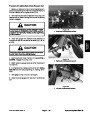
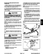
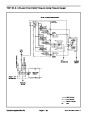
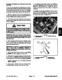
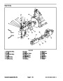
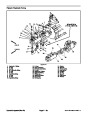
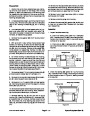
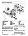
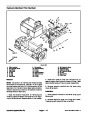
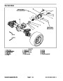
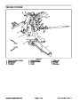
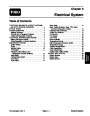
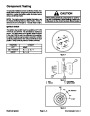
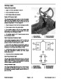
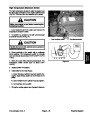
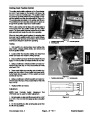
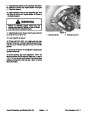
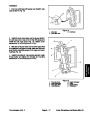
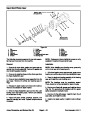
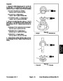
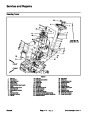
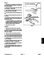
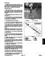
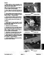
A. Lubricate the axle case support bushing with a
thin coat of grease and slide axle case support onto
knuckle pin.
1
B. Position support shims that were removed during
disassembly between axle case support and axle
case. Install mounting screws into axle case. Slowly
tighten screws while frequently checking for clear-
ance (vertical endplay) between axle case support
and knuckle pin. If binding of components is noted
before screws are fully tightened, add additional sup-
port shims. Torque screws from 57 to 67 ft−lb (77 to
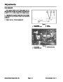
VERTICAL
ENDPLAY
6
5
2
3
91
N−m).
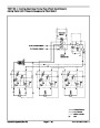
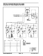
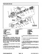
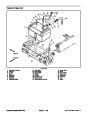
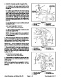
Figure 20
4.
5.
6.
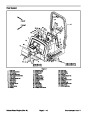
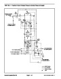
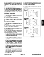
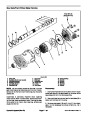
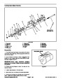
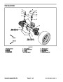
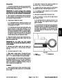
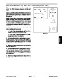
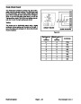
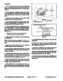
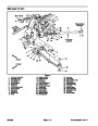
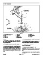
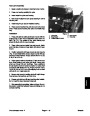
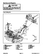
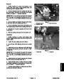
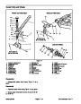
C. Use dial indicator to measure vertical endplay of
axle case (Fig. 20).
1.
2.
3.
Axle case support
Axle case
Bevel gearcase
Dial indicator
Knuckle pin
Support shim location
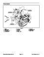
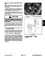
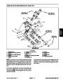
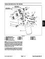
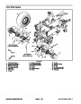
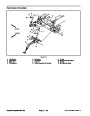
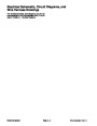
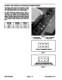
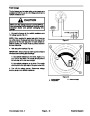
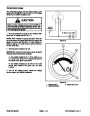
AXLE CASE ASSEMBLY ENDPLAY:
0.001
to 0.008 in. (0.02 to 0.20 mm)
3
2
D. Adjust endplay by increasing or reducing number
of axle case support shims.
1
NOTE: Axle case support shims are available in
0.004
in. (0.1 mm), 0.008 in. (0.2 mm), and 0.016 in.
4
(0.4
mm) thickness.
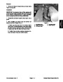
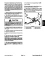
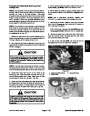
6.
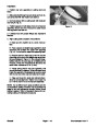
After correct support shims have been determined,
remove mounting screws, apply heavy strength thread−
locking compound to screw threads, reinstall screws,
and torque from 57 to 67 ft−lb (77 to 91 N−m).
5
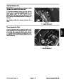
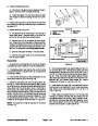
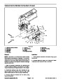
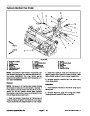
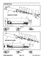
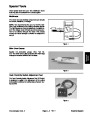
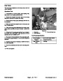
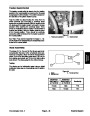
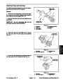
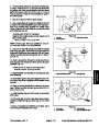
IMPORTANT:
Correct engagement between bevel
gears is critical to axle performance and durability.
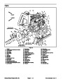
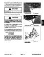
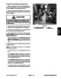
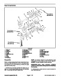
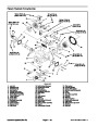
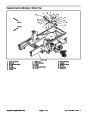
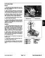
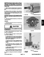
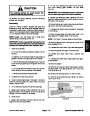
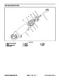
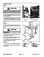
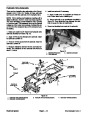
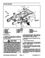
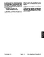
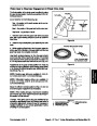
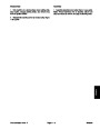
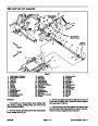
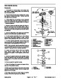
7.
Temporarily install the bevel gear case/axle case as-
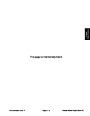
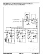
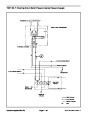
Figure 21
sembly on the axle support. Position a dial indicator at
the tooths center. Prevent the axle from turning and
measure the upper bevel gear to differential shaft gear
backlash (Fig. 21).
1.
2.
3.
Axle support
Upper bevel gear
Differential shaft gear
4.
5.
Dial indicator
Axle bearing shims
4
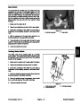
UPPER BEVEL GEAR BACKLASH:
5
0.004
to 0.016 in. (0.10 to 0.40 mm)
1
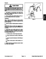
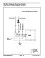
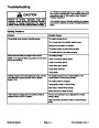
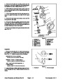
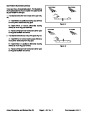
8.
Adjust backlash by increasing or reducing axle bear-
ing shim thickness (see Differential Shafts in this section
of this manual).
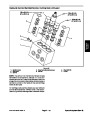
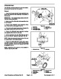
NOTE: Axle bearing shims are available in 0.004 in.
(0.1
mm), 0.008 in. (0.2 mm), and 0.020 in. (0.5 mm)
thickness.
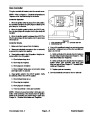
3
2
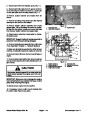
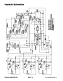
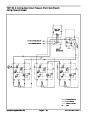
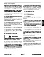
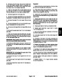
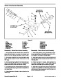
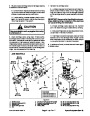
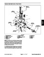
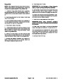
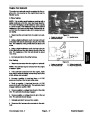
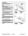
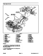
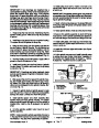
Figure 22
1.
2.
3.
Axle cover assembly
Lower bevel gear
Axle gear
4.
5.
Dial indicator
Axle bearing shims
Axles, Planetaries, and Brakes (Rev. B)
Page 6 − 18
Groundsmaster 4000−D
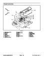
| Categories | Lawn Mower Manual, Toro Lawn Mower Manual |
|---|---|
| Tags | Toro Groundsmaster 4000 D |
| Download File |
|
| Document Type | Service Manual |
| Language | English |
| Document File Type | |
| Publisher | toro.com |
| Wikipedia's Page | Toro Company |
| Copyright | Attribution Non-commercial |
(0 votes, average: 0 out of 5)