


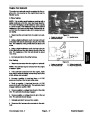


Disassembly
1.
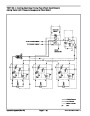
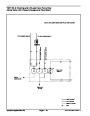
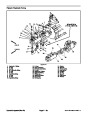
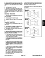
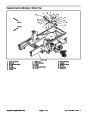
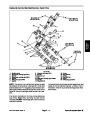
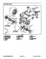
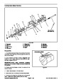
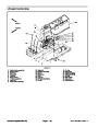
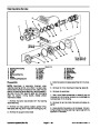
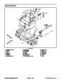
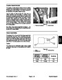
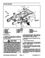
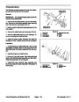
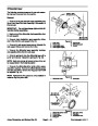
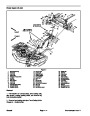
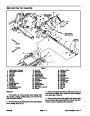
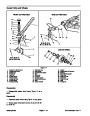
Disassemble rear arm assembly using Figure 7 as a
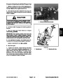
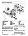
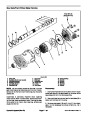
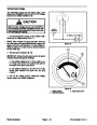
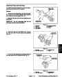
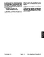
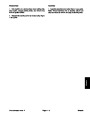
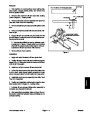
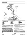
guide. Note: early models use rear arm components as
shown in Figure 9. On these models, roll pin removal will
allow coupler to be separated from spring shaft.
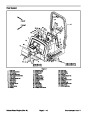
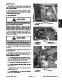
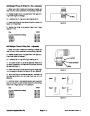
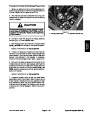
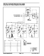
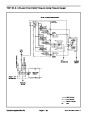
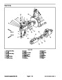
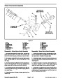
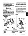
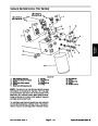
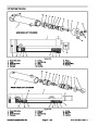
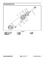
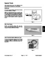
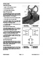
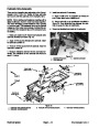
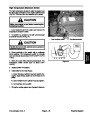
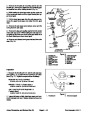
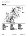
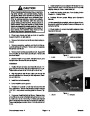
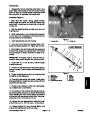
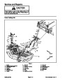
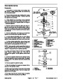
Assembly (Figure 7)
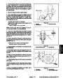
1.
Slide large flat washer, spring, plastic bearing,
5
(13.6
.370” + .075”
cm + .2 cm)
1
another large flat washer and small flat washer onto
spring shaft. Loosely secure components to shaft with
one jam nut.
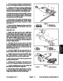
2.
Slide the straight bushing and plate onto other end
of spring shaft.
2
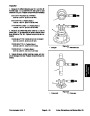
3.
While holding flats on end of spring shaft, rotate jam
nut (on other end of assembly) until components are
snug but spring is not compressed.
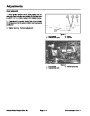
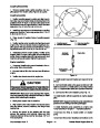
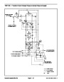
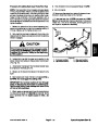
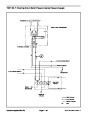
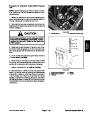
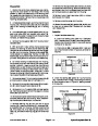
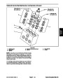
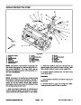
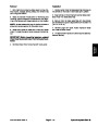
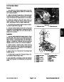
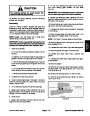
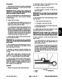
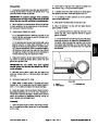
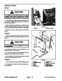
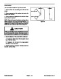
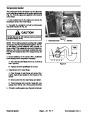
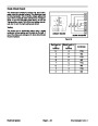
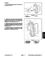
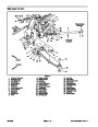
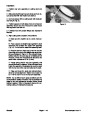
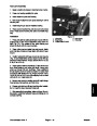
Figure 8
2.
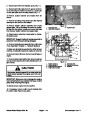
4.
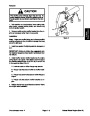
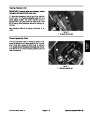
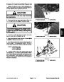
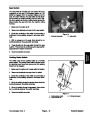
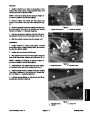
Insert assembly into rear arm housing.
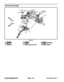
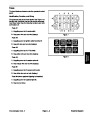
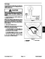
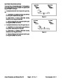
1.
Damper link
Clevis pin
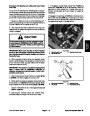
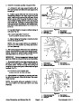
5.
From open end of rear arm housing, insert a 3/4”
socket onto spring shaft jam nut. Tighten jam nut fully.
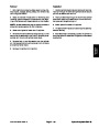
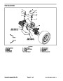
EARLY MODELS
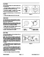
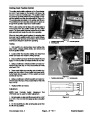
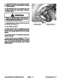
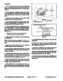
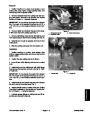
6.
Mount plate to rear arm housing with two cap screws
2
and lock nuts. Grasp end of spring shaft. Push inward
and pull outward on shaft to determine endplay in as-
sembly.
3
4
5
1
4
3
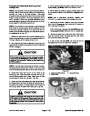
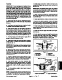
IMPORTANT: All endplay must be removed from as-
8
sembly to allow proper operation and ensure long life.
7.
in shaft is removed.
Loosen jam nut, 1/2 turn at a time, until all endplay
10
6
8.
Remove two cap screws and nuts securing plate to
rear arm housing. Remove spring shaft assembly from
housing.
7
9
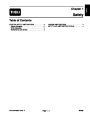
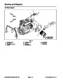
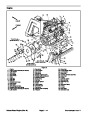
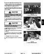
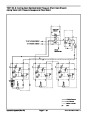
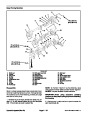
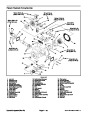
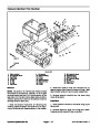
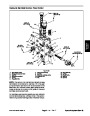
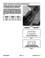
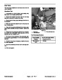
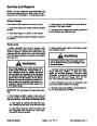
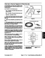
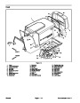
Figure 9
9.
and tighten to lock adjustment.
Thread remaining jam nut onto end of spring shaft
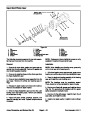
1.
Rear arm
6.
7.
8.
9.
Plate
2.
3.
4.
5.
Spring shaft
Flat washer
Bushing
Coupler
Roll pin
Jam nut
10.Thoroughly
shaft assembly into housing and secure plate with four
cap screws and lock nuts.
pack spring with grease. Install spring
Compression spring
10. Rod end
11.
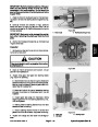
Thread rod end with jam nut into end of spring shaft.
Do not tighten jam nut at this time.
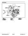
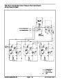
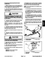
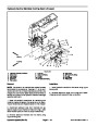
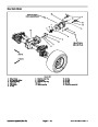
12.If
rod ends (31) were removed from damper (30), ap-
ply thread locking compound to damper shaft threads
before installing rod ends. Secure damper to bellcrank
and rear arm with cap screws and lock nuts. Torque fas-
teners from 22 to 27 ft−lb (30 to 37 N−m).
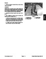
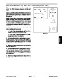
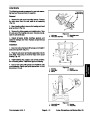
13.If
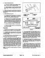
damper link was disassembled, adjust the length
of the link to 5.370” + .075” (13.6 cm + .2 cm) (Fig. 8).
14.If
damper springs (37) were removed, tighten lock
nuts so that bushings (36) are free to rotate.
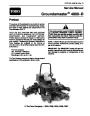
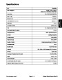
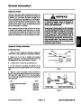
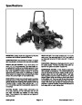
Groundsmaster 4000−D
Page 7 − 9
Chassis
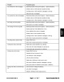
| Categories | Lawn Mower Manual, Toro Lawn Mower Manual |
|---|---|
| Tags | Toro Groundsmaster 4000 D |
| Download File |
|
| Document Type | Service Manual |
| Language | English |
| Document File Type | |
| Publisher | toro.com |
| Wikipedia's Page | Toro Company |
| Copyright | Attribution Non-commercial |
(0 votes, average: 0 out of 5)