


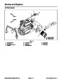
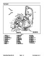


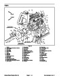


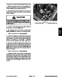

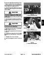
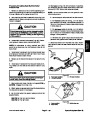
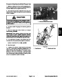
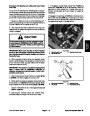


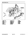

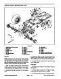
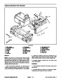
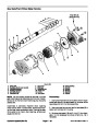
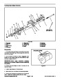


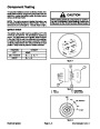

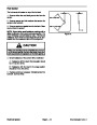


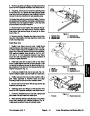
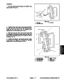
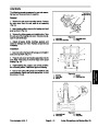
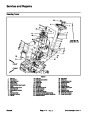


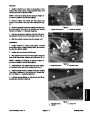


3.
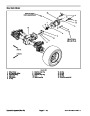
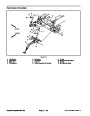
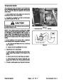
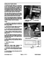
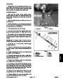
Remove pump from vise, hold pump in hands and
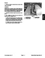
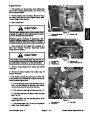
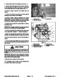
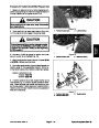
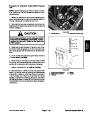
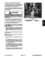
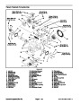
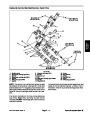
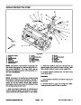
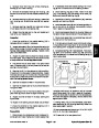
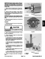
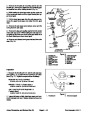
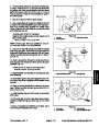
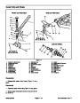
Inspection
bump shaft against wooden block to separate front
pump sections. Front body (10) will remain with either
front plate (15) or front adapter plate (23).
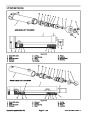
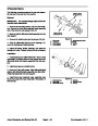
1.
Clean and dry all pump components. Remove nicks
and burrs from all parts with emery cloth.
2.
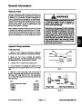
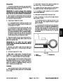
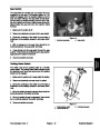
Also check for damaged keyway, on drive shaft, that
drives the slip fit gears of the pump.
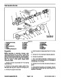
Check spline drive shaft for twisted or broken teeth.
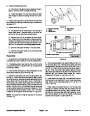
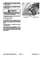
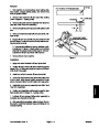
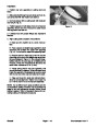
4.
with soft face hammer until the front body separates.
Remove idler gear from front plate or adapter plate.
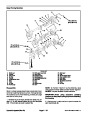
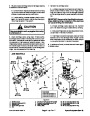
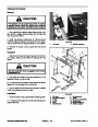
Place front idler gear (16) into gear pocket and tap
3.
bushing points and seal area for rough surfaces and ex-
cessive wear.
Inspect both the drive gear and idler gear shafts at
5.
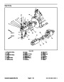
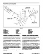
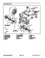
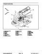
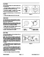
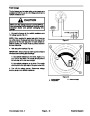
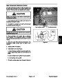
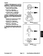
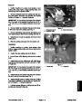
Remove plug (8) from front plate (15).
6.
Remove front adapter plate (23) from front body (10)
by tapping on the adapter plate with a soft face hammer.
4.
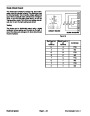
Replace gear assembly if shaft measures less than
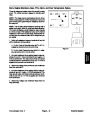
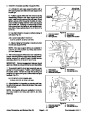
7.
(17).
Remove idler gear (21), slip fit gear (18), and key
.873inch(22.17mm)inbushingarea.(Onegearassem-
bly may be replaced separately; shafts and gears are
available as assemblies only. The slip fit gear is avail-
able separately).
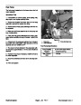
8.
ping on backplate with soft face hammer.
Remove backplate (27) from rear body (26) by tap-
5.
Inspect gear faces for scoring or excessive wear.
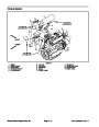
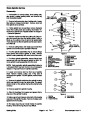
9.
Remove rear idler gear (25), slip fit gear (20) and key
(22).
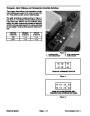
6. Replace gear assembly if gear width is below
1.181
inch (30.00 mm).
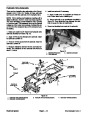
10.Remove
plate (24).
drive gear assembly (11) from rear adapter
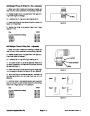
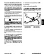
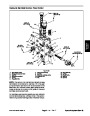
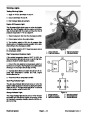
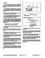
7. Assure that snap rings are in grooves on either side
of drive and idler gears.
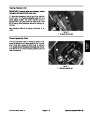
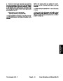
11.
Place rear idler gear assembly (25) back into gear
pocket and tap protruding end with soft face hammer to
removerearbody(26)fromthebackplateassembly(27)
or the rear adapter plate (24).
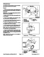
8. If any edge of gear teeth is sharp, break edge with
emery cloth.
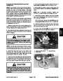
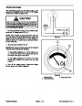
9.
Oil groove in bushings in front plate, backplate and
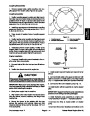
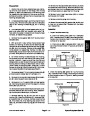
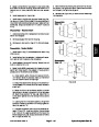
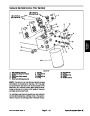
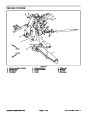
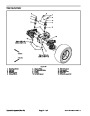
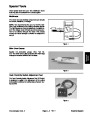
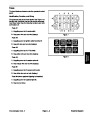
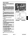
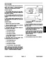
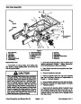
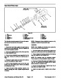
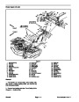
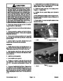
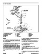
IMPORTANT: Note position of the open and closed
side of the wear plates before removing.
adapter plates shouldbein linewith dowelpin holes and
180degreesapart.Thispositionstheoilgroovesclosest
to respective dowel pin holes.
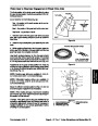
12.Remove
the wear plates (12) and o--rings (4) from
front plate (15), front adapter plate (23), and rear adapt-
er plate (24).
10.Replace the backplate, front plate or adapter plates
if l.D. of bushings exceed .879 inch (22.33mm) (Bush-
ings are not available as separate items).
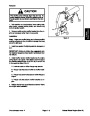
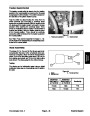
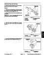
13.Remove
backup gaskets (14) and pressure seals
(13)
sharp tool.
from wear plates (15) by carefully prying out with a
11.Bushings in front plate and backup gasket side of
adapter plates should be flush with face of plate.
IMPORTANT: Do not damage the seal bore in the
front plate during seal removal.
12.Check for scoring on face of backplate and adapter
plates. Replace if wear exceeds .0015 inch (.038mm).
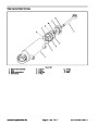
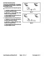
14.Remove
plate (15).
shaft seal (1) and washer (2) from front
plug (7) and washer (9) from rear adapter
proportional valve (6) from backplate as-
13.Check bodies inside gear pockets for excessive
scoring or wear.
15.Remove
plate (24).
14.Replace bodies if l.D. of gear pockets exceeds
2.100 inch (53.34mm).
16.Remove
sembly (27).
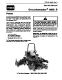
Groundsmaster 4000--D
Page 4 -- 55
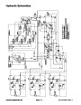
Hydraulic System (Rev. B)
| Categories | Lawn Mower Manual, Toro Lawn Mower Manual |
|---|---|
| Tags | Toro Groundsmaster 4000 D |
| Download File |
|
| Document Type | Service Manual |
| Language | English |
| Document File Type | |
| Publisher | toro.com |
| Wikipedia's Page | Toro Company |
| Copyright | Attribution Non-commercial |
(0 votes, average: 0 out of 5)