
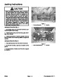


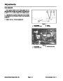


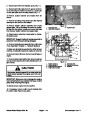
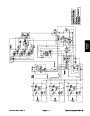


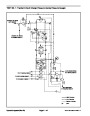

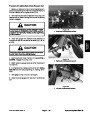
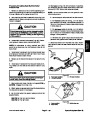
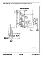
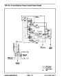


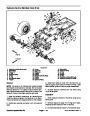
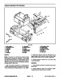
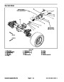
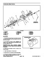


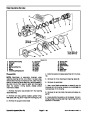
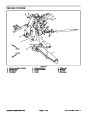

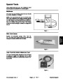
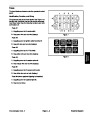


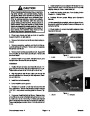
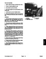


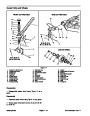


Pinion Gear to Ring Gear Engagement (4 Wheel Drive Axle)
The final position of the pinion gear is verified by using
the gear contact pattern method as described in the fol-
lowing procedure.
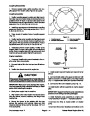
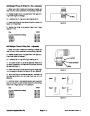
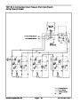
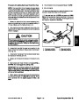
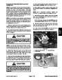
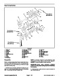
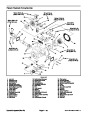
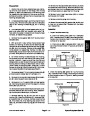
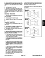
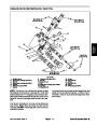
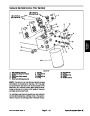
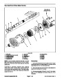
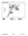
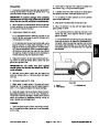
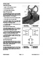
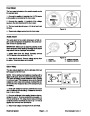
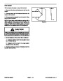
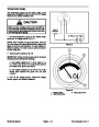
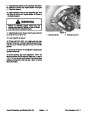
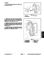
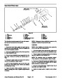
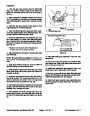
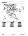
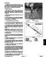
PROFILE
TOP LAND
GEAR TOOTH DEFINITIONS (Fig. 39):
Toe − the portion of the tooth surface at the end to-
TOE
LENGTHWISE
BEARING
ARC
wards the center.
Heel − the portion of the gear tooth at the outer end.
Top Land − top surface of tooth.
HEEL
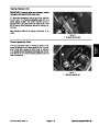
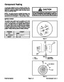
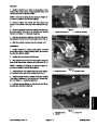
1.
side, with a gear marking compound, such as DyKem
Steel Blue.
Paint the teeth of the ring gear, both drive and coast
R
ROOT
Figure 39
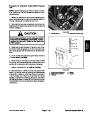
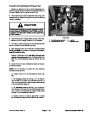
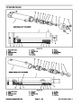
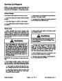
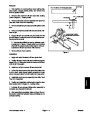
2.
Install the input shaft/pinion gear assembly into axle
case.
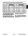
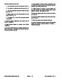
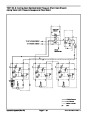
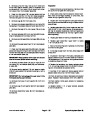
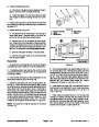
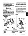
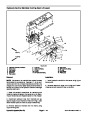
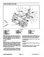
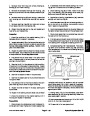
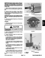
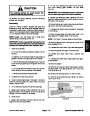
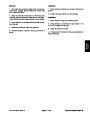
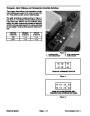
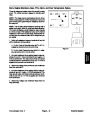
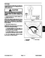
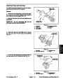
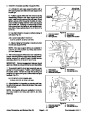
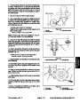
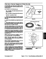
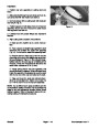
More than 35% total tooth contact
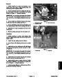
3.
While applying a light load to the ring gear, rotate the
pinion gear in the direction of forward travel until the ring
gear has made one complete revolution.
Ideal tooth contact observed on the ring gear should
cover more than 35% of each tooth surface. The contact
area should be in the center of each tooth and extend 1/3
to 1/2 way across each tooth from the toe end (Fig. 40).
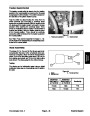
1/3 to 1/2 of entire width
from small end of tooth
Figure 40
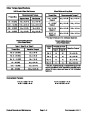
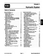
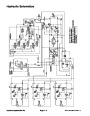
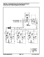
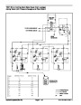
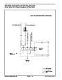
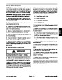
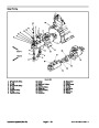
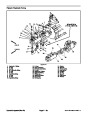
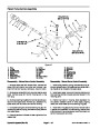
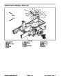
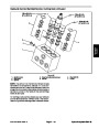
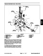
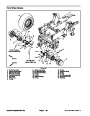
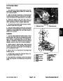
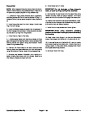
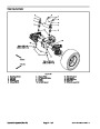
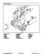
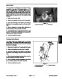
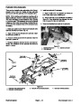
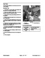
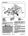
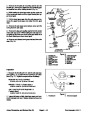
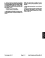
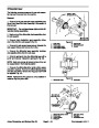
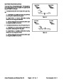
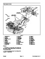
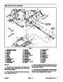
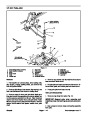
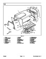
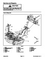
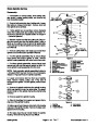
Adjustments to the gear contact position are made by
moving the input shaft/pinion gear (bearing case shims)
or by moving the differential gear case (differential bear-
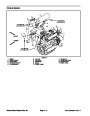
ing shims) (Fig. 41).
4
3
NOTE: Bearing case shims are available in 0.004 in.
(0.10
mm) and 0.008 in. (0.20 mm) thickness.
NOTE: Differential bearing shims are available in
0.004
(0.40
in. (0.10 mm), 0.008 in. (0.20 mm) and 0.016 in.
mm) thickness.
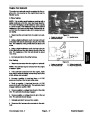
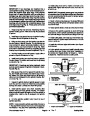
Study the different contact patterns (Figs. 42 and 43)
and correct gear engagement as necessary.
2
NOTE: When making changes, note that two variables
are involved (see Gear Pattern Movement Summary in
this section of this manual).
1
Example: If the pinion gear to ring gear backlash is set
correctly to specifications and the bearing case shim is
changed to adjust tooth contact, it may be necessary to
readjust backlash to the correct specification before
checking the contact pattern.
Figure 41
1.
2.
3.
Input shaft/pinion gear
Bearing case shims
Differential gear case
4.
Differential bearing
shims
Groundsmaster 4000−D
Page 6 − 27 Rev. E Axles, Planetaries, and Brakes (Rev. B)
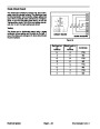
| Categories | Lawn Mower Manual, Toro Lawn Mower Manual |
|---|---|
| Tags | Toro Groundsmaster 4000 D |
| Download File |
|
| Document Type | Service Manual |
| Language | English |
| Document File Type | |
| Publisher | toro.com |
| Wikipedia's Page | Toro Company |
| Copyright | Attribution Non-commercial |
(0 votes, average: 0 out of 5)