


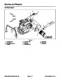


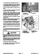
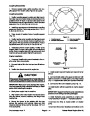
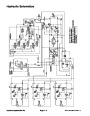
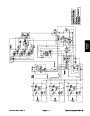


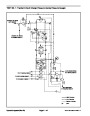

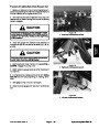
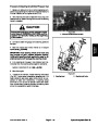
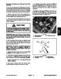


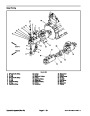

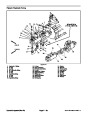
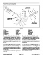
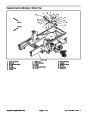

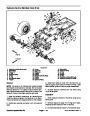
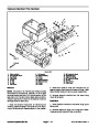
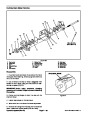
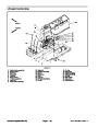


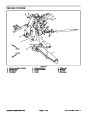


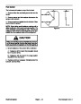
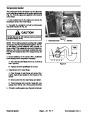


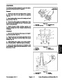
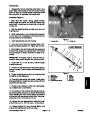
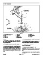
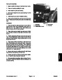

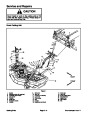

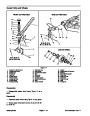


Lower Cutting Unit
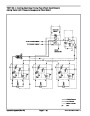
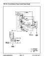
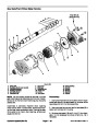
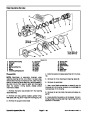
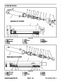
A three section gear pump is coupled to the piston (trac-
tion)pump.Thegearpumpsection farthestfromthepis-
ton pump supplies hydraulic flow to both the lift/lower
control valve and the steering control valve. Hydraulic
flow from this pump section is delivered to the circuits
through a proportional flow divider. This pump section
takes its suction from the hydraulic reservoir.
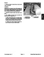
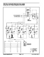
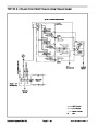
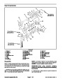
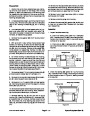
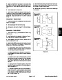
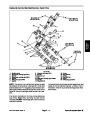
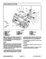
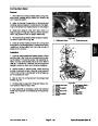
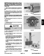
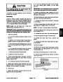
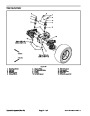
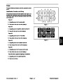
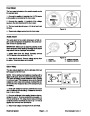
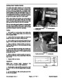
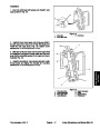
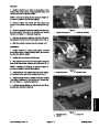
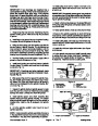
To lower the front cutting unit, the center lift lever on the
lift/lowercontrolvalveispushedtoallowvalveshiftinthe
lift/lowercontrol.Thisvalvechangeallowsapassagefor
oilflowfromtherodendofthefrontdeckliftcylinder.The
weight of the cutting deck causes the lift cylinder to ex-
tend, and lower the cutting unit. Oil from the rod end of
thecylinderisallowedtoreturntothetractionchargecir-
cuit.Whentheliftleverisreleased,theliftcylinderisheld
in position.
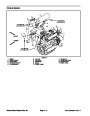
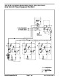
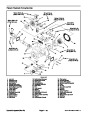
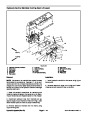
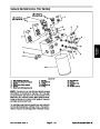
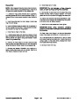
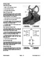
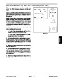
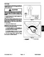
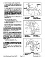
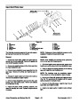
When the cutting units are in a stationary position, flow
from the gear pump is by--passed through the lift/lower
control valve, counterbalance manifold, oil filter, and
traction charge circuit.
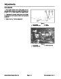
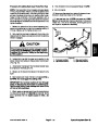
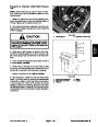
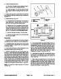
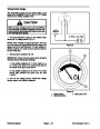
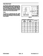
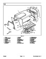
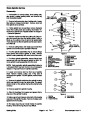
The drop speed of the front cutting units is regulated by
an adjustable flow control valve that is located in the hy-
draulic lines between the lift/lower control valve and the
front deck lift cylinders.
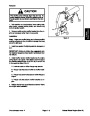
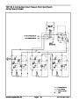
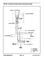
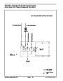
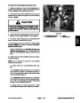
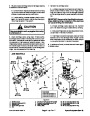
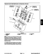
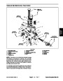
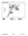
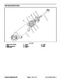
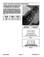
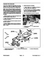
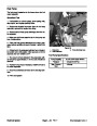
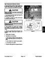
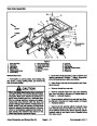
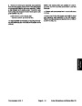
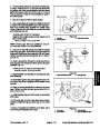
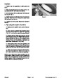
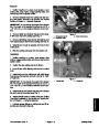
To lower a side cutting unit, the appropriate lift lever on
the lift/lower control valve is pushed to allow valve shift
in the lift/lower control. This valve change causes a
valve shift in the counterbalance manifold and oil flow to
the rod end of the lift cylinder. Higher hydraulic pressure
against the rod end of the cylinder causes the shaft to
retract,andlowerthecuttingunit.Oilfromthepistonend
of the cylinder returns to the traction charge circuit.
When the lift lever is released, the lift cylinder is held in
position.
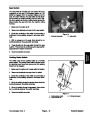
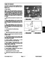
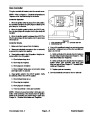
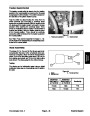
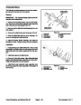
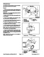
An adjustable counterbalance valve maintains back
pressure on the side deck lift cylinders. A relief valve lo-
catedinthelift/lowercontrolvalvelimitscircuitpressure.
Excess circuit flow is routed to the oil filter and then to
the traction charge circuit.
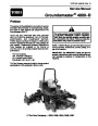
Groundsmaster 4000--D
Page 4 -- 11
Hydraulic System (Rev. B)
| Categories | Lawn Mower Manual, Toro Lawn Mower Manual |
|---|---|
| Tags | Toro Groundsmaster 4000 D |
| Download File |
|
| Document Type | Service Manual |
| Language | English |
| Document File Type | |
| Publisher | toro.com |
| Wikipedia's Page | Toro Company |
| Copyright | Attribution Non-commercial |
(0 votes, average: 0 out of 5)