


8.
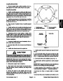
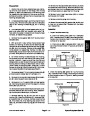
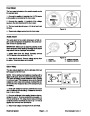
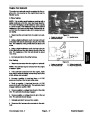
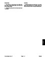
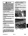
corner of 4WD hydraulic manifold to rear frame mount.
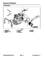
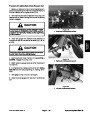
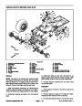
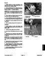
Remove cap screw and flange nut that secures front
1
2
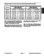
9.
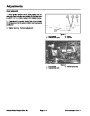
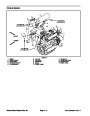
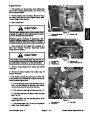
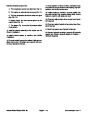
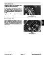
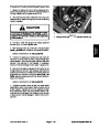
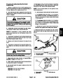
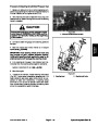
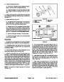
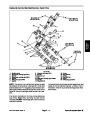
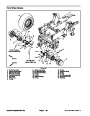
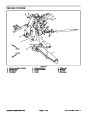
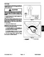
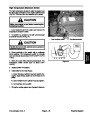
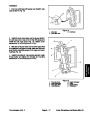
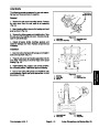
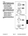
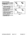
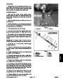
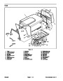
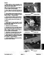
If required, remove tie rod ends from steering arms
3
4
on rear axle (Fig. 10). Remove the cotter pins and castle
nuts from the tie rod ball joints. Use a ball joint fork and
remove the tie rod ends from the axle steering arms.
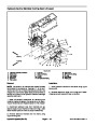
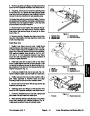
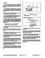
10.Support
rear axle to prevent it from falling. Remove
six cap screws, flat washers, and flange nuts that secure
rear frame mount to equipment frame. Lower rear axle
and rear frame mount from machine.
5
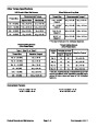
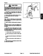
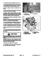
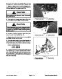
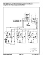
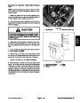
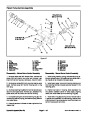
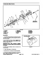
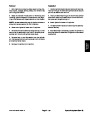
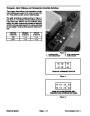
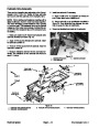
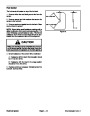
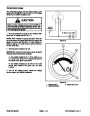
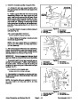
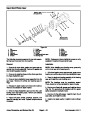
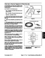
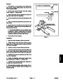
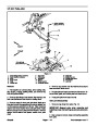
11.
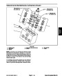
Remove lock nut and washer from pivot pin that at-
taches rear axle to rear frame mount. Remove washer
head screw that secures flange of pivot pin to frame
mount (Fig. 11).
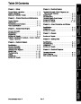
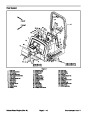
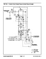
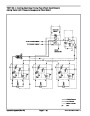
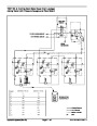
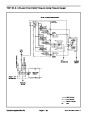
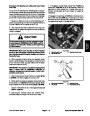
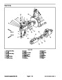
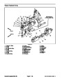
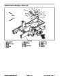
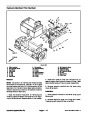
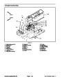
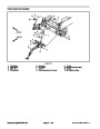
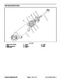
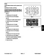
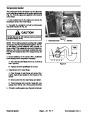
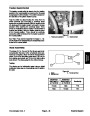
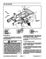
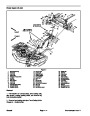
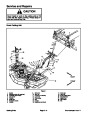
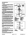
Figure 9
12.Remove
rear axle. Note location of thrust washers on both ends
of axle mounting boss.
pivot pin. Separate rear frame mount from
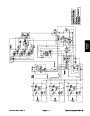
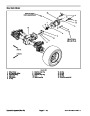
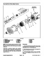
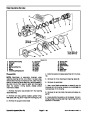
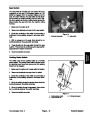
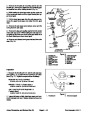
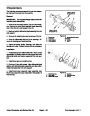
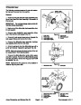
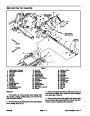
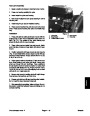
1.
2.
3.
Hydraulic hose
Hydraulic hose
Hydraulic tube
4.
5.
Hydraulic tube
Rear frame mount
Install Rear Axle
4
5
3
2
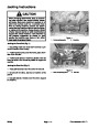
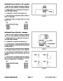
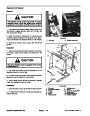
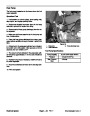
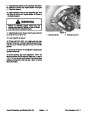
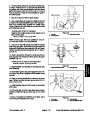
1.
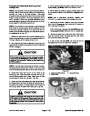
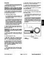
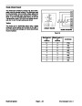
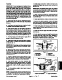
Position rear frame mount to axle. Install thrust
washers between axle boss and frame mount. The thin-
ner thrust washer should be installed on the hydraulic
motor end of the axle (toward the rear of the machine).
With washers installed, there should be .002” to .020”
1
(.05
mount and axle mounting boss. Add thrust washers if
needed to adjust clearance.
mm to .51 mm) clearance between rear frame
6
2.
Install axle pivot pin to secure axle to rear frame
mount. Install washer and lock nut onto pivot pin. Lock
nut should be tightened enough to allow pivot pin to ro-
tate (maximum 70 ft−lb (94 N−m)). Secure pivot pin with
washer head screw (Fig. 11).
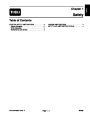
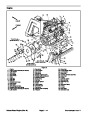
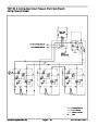
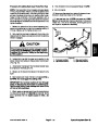
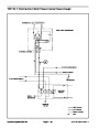
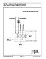
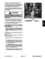
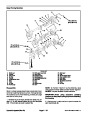
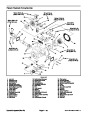
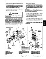
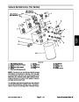
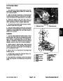
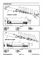
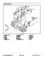
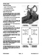
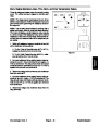
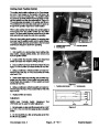
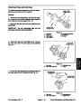
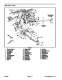
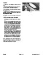
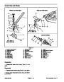
Figure 10
4.
5.
6.
1.
2.
3.
Tie rod
Dust cover
Cotter pin
Castle nut
Tie rod end
Steering arm (LH)
3.
If removed, install the tie rod to rear axle (Fig. 10).
Tighten ball joint castle nuts and install new cotter pins.
4.
jack. Raise assembly to machine frame and align
mounting holes of rear mount and machine frame.
Position axle and rear mount under machine with a
2
1
5.
Secure rear mount to frame with six cap screws, flat
washers, and flange nuts.
6.
Install cap screw and flange nut that secures front
corner of 4WD hydraulic manifold to rear frame mount.
7.
joint castle nuts and install new cotter pins.
If removed, install the tie rod to rear axle. Tighten ball
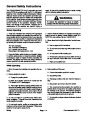
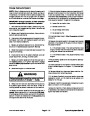
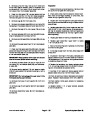
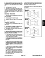
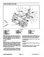
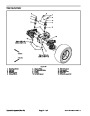
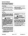
Figure 11
1.
Pivot pin
2.
Washer head screw
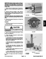
8.
Attach steering cylinder hydraulic tubes to rear frame
mount with washers and bulkhead locknuts (Fig. 9).
Install steering cylinder hoses to hydraulic tubes.
Groundsmaster 4000−D
Page 6 − 13
Axles, Planetaries, and Brakes (Rev. B)
| Categories | Lawn Mower Manual, Toro Lawn Mower Manual |
|---|---|
| Tags | Toro Groundsmaster 4000 D |
| Download File |
|
| Document Type | Service Manual |
| Language | English |
| Document File Type | |
| Publisher | toro.com |
| Wikipedia's Page | Toro Company |
| Copyright | Attribution Non-commercial |
(0 votes, average: 0 out of 5)