


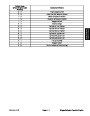


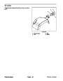

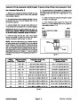


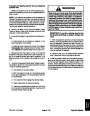


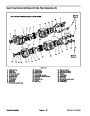


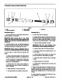


Relay (Five Terminals)
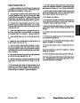
WorkmanHDseriesvehiclesuseanumberofrelaysthat
have five (5) terminals:
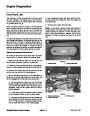
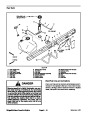
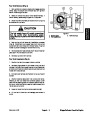
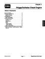
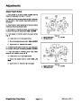
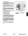
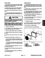
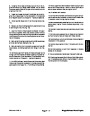
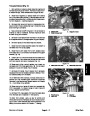
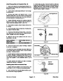
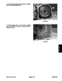
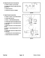
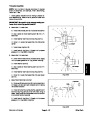
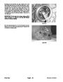
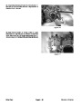
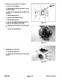
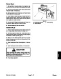
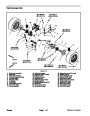
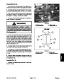
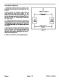
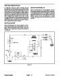
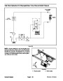
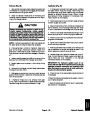
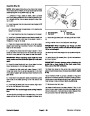
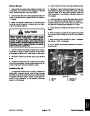
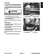
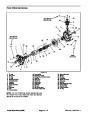
4. Connect multimeter (ohms setting) leads to relay ter-
minals30and87(Fig.22).Groundterminal86andapply
+12
VDC to terminal 85. The relay should make and
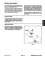
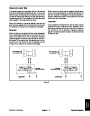
The clutch relay on Workman HD, HDX and HDX--D ve-
hicles ensures that the clutch pedal is depressed before
the engine starter can be engaged.
break continuity between terminals 30 and 87 as +12
VDC is applied and removed from terminal 85.
5.
lead from terminal 87.
Disconnect voltage from terminal 85 and multimeter
The start relay on Workman HD, HDX and HDX--D ve-
hicles is used to energize the starter solenoid so that the
engine can be started.
6. Connect multimeter (ohms setting) leads to relay ter-
minals 30 and 87A. Apply +12 VDC to terminal 85. The
relay should make and break continuity between termi-
nals 30 and 87A as +12 VDC is applied and removed
from terminal 85.
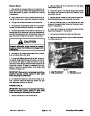
The fan relay on Workman HDX and HDX--D vehicles
causes the engine cooling fan to rotate when the relay
is energized.
The fuel pump relay on Workman HDX vehicles allows
current to the fuel pump when the relay is energized.
7.
relay terminals.
Disconnect voltage and multimeter leads from the
ThekillrelayonWorkmanHDvehiclesallowstheengine
to run as long as the relay is energized. If the ignition
switch is in the OFF position or the transmission lockout
switches are allopen, the relay will notbe energized and
the engine will cease running.
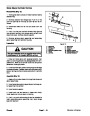
8.
Replacerelayiftestingdeterminesthatrelayisfaulty.
9. After testing is complete, secure relay to machine
and connect wire harness connector to relay.
1
2
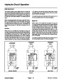
ThedifferentialanddifferentialdelayrelaysonWorkman
HDX and HDX--D 4WD vehicles are used to make sure
thatthefrontwheeldrivedifferentialsolenoidisnotener-
gizedwhentheclutchisdisengagedduringenginestart-
ing and transaxle shifting.
3
1
2
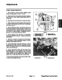
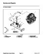
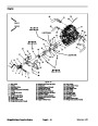
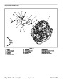
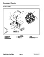
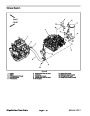
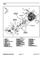
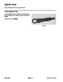
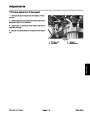
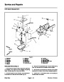
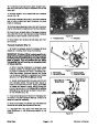
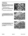
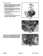
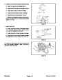
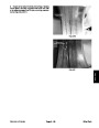
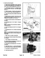
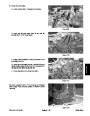
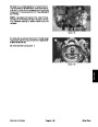
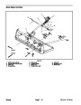
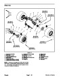
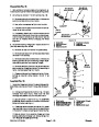
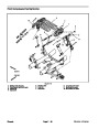
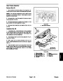
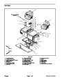
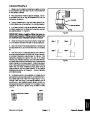
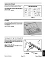
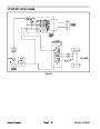
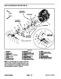
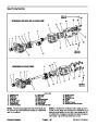
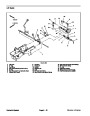
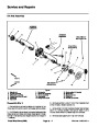
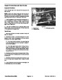
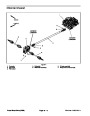
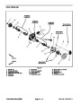
The clutch relay and differential relays (if equipped) are
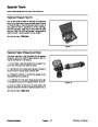
located behind the dash panel. The other relays are at-
tachedtotherelaybracketundertherightsideofthebed
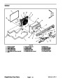
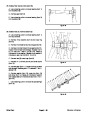
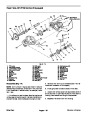
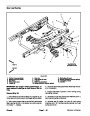
near the rear axle (Fig. 21).
HDX MODELS
HDX--D MODELS
4
1
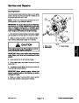
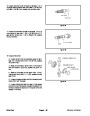
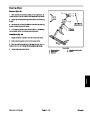
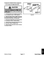
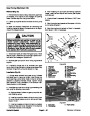
Testing
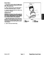
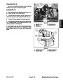
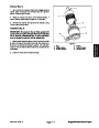
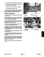
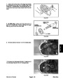
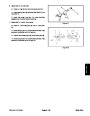
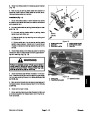
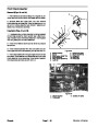
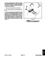
1.
Park machine on a level surface and apply parking
brake. If relay is located on relay bracket, raise bed and
install bed support on bed lift cylinder to prevent bed
fromlowering.Stopengineandremovekeyfromignition
switch.
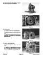
HD MODELS
Figure 21
1.
2.
Start relay
Fan relay
3.
4.
Fuel pump relay
Kill relay
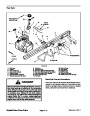
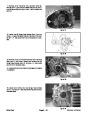
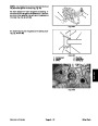
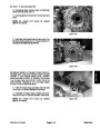
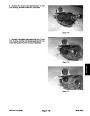
2.
Locate relay that is to be tested and disconnect the
wire harness connector from the relay. Remove relay
from machine for easier testing.
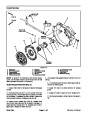
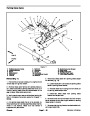
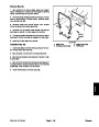
NOTE: Prior to taking small resistance readings with a
digital multimeter, short the meter test leads together.
The meter will display a small resistance value (usually
86
87A
87
0.5
ohms or less). This resistance is due to the internal
resistance of the meter and test leads. Subtract this val-
ue from from the measured value of the component you
are testing.
85
30
3.
sistance between terminals 85 and 86 (Fig. 22). Resist-
ance should be between 70 and 90 ohms.
Using a multimeter (ohms setting), measure coil re-
Figure 22
Workman HD Series
Page 8 -- 17
Electrical System
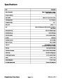
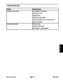
| Categories | Lawn Mower Manual, Sprinkler and Irrigation Manuals, Toro Sprinkler and Irrigation Manuals |
|---|---|
| Tags | Toro 09173SL |
| Download File |
|
| Document Type | Service Manual |
| Language | English |
| Product Brand | Toro. Customer Service Representatives are available by phone:
Monday - Friday 7:30 a.m. to 9:00 p.m. (CDT) - Saturday 8:00 a.m. to 8:00 p.m. (CDT) - Sunday 10:00 a.m. to 8:00 p.m. (CDT)
Canada 1-888-225-4886 USA 1-888-384-9939, Lawn Mower |
| Document File Type | |
| Publisher | toro.com |
| Wikipedia's Page | Toro Company |
| Copyright | Attribution Non-commercial |
(0 votes, average: 0 out of 5)