


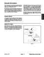
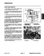


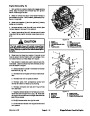
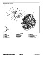
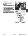
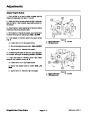
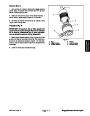
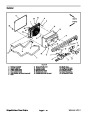
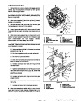


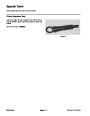
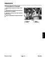
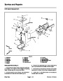


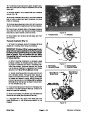
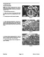


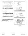
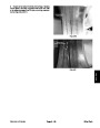


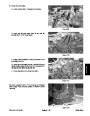
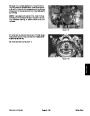


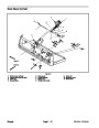
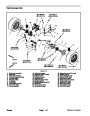


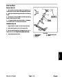


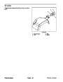


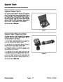


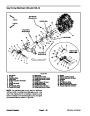

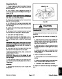
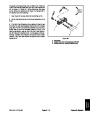


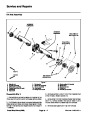
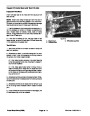
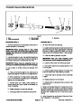


Glow Plug Timer (Workman HDX--D)
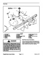
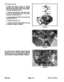
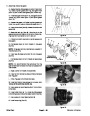
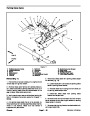
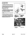
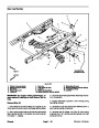
The glow plug timer is attached to the relay bracket un-
der the right side of the bed near the rear axle (Fig. 36).
1
2
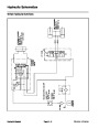
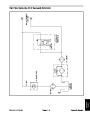
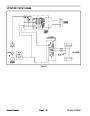
NOTE: Refer to electrical schematic and circuit draw-
ings in Chapter 11 -- Electrical Drawings when trouble-
shooting the glow plug timer.
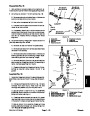
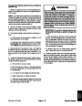
Glow Plug Timer Operation
1.
position, the timer energizes the glow plugs and illumi-
nates the glow lamp for approximately five (5) seconds.
When the ignition switch is initially turned to the ON
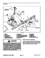
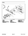
Figure 36
2.
tion, the glow plugs will energize and the glow lamp will
light for fifteen (15) to twenty (20) seconds.
Whenthe ignition switch isturned tothe STARTposi-
1.
HDX--D relay bracket
2.
Glow plug timer
3.
ON, the glow plugs will energize and the glow lamp will
light for approximately fifteen (15) seconds.
When the ignition switch is released from START to
1
4
1
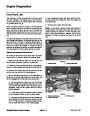
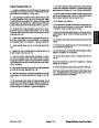
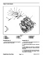
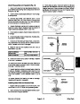
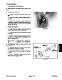
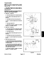
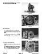
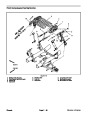
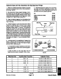
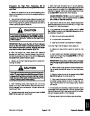
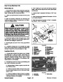
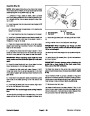
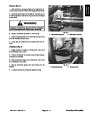
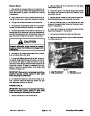
Glow Plug Timer Checks
5
6
2
3
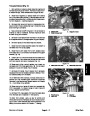
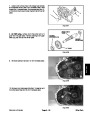
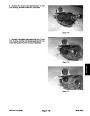
1.
2.
Make sure there is power from the battery.
2
Disconnect wire harness connector from the engine
run solenoid to prevent the engine from starting.
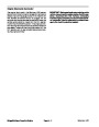
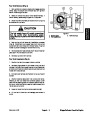
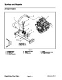
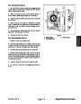
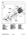
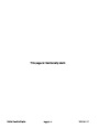
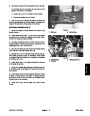
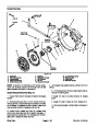
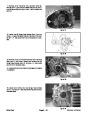
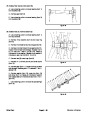
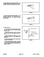
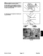
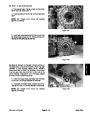
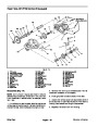
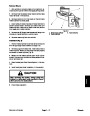
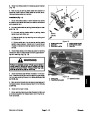
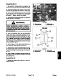
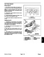
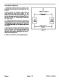
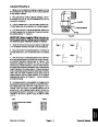
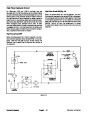
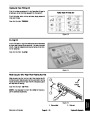
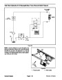
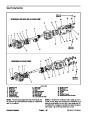
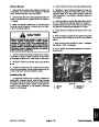
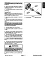
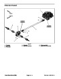
TIMER
CONNECTIONS
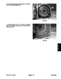
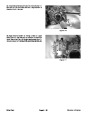
3.
PlaceignitionswitchintheONposition.Verifythefol-
lowing while in the ON position:
A. Dash glow indicator lamp is illuminated.
B. Glow relay is energized.
+12V
START
GLOW
4
5
6
1
2
3
PINK
GRAY
GROUND
VIOLET
BLACK
C. Glow plugs are energized.
D. Glow indicator lamp goes out and glow plugs de--
energize after approximately five (5) seconds.
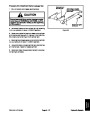
Figure 37
1.
Glow plug timer
2.
Timer terminals
4.
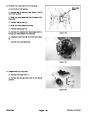
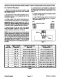
PlaceignitionswitchintheSTARTposition.Verifythe
5.
If any of the conditions in step 3 or step 4 are not met:
following while in the START position:
A. Dash glow indicator lamp is illuminated.
B. Glow relay is energized.
A. Verify continuity of the circuitry from the battery to
the glow relay and glow plugs (see electrical sche-
matic in Chapter 11 -- Electrical Drawings).
B. Verify continuity of the circuitry from the battery to
ignition switch, glow plug timer, glow indicator lamp,
glow relay and ground (see electrical schematic in
Chapter 11 -- Electrical Drawings).
C. Glow plugs are energized.
D. Power exists at terminal 5 of the glow plug timer.
NOTE: If there is no power at terminal 5 of the glow
plug timer, verify continuity of the circuitry from the
ignition switch to the timer and perform step 4 again
(see electrical schematic in Chapter 11 -- Electrical
Drawings).
C. Replace parts as necessary.
6.
After testing is complete, connect wire harness con-
nector to the engine run solenoid.
Workman HD Series
Page 8 -- 25
Electrical System
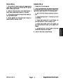
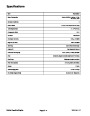
| Categories | Lawn Mower Manual, Sprinkler and Irrigation Manuals, Toro Sprinkler and Irrigation Manuals |
|---|---|
| Tags | Toro 09173SL |
| Download File |
|
| Document Type | Service Manual |
| Language | English |
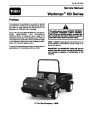
| Product Brand | Toro. Customer Service Representatives are available by phone:
Monday - Friday 7:30 a.m. to 9:00 p.m. (CDT) - Saturday 8:00 a.m. to 8:00 p.m. (CDT) - Sunday 10:00 a.m. to 8:00 p.m. (CDT)
Canada 1-888-225-4886 USA 1-888-384-9939, Lawn Mower |
| Document File Type | |
| Publisher | toro.com |
| Wikipedia's Page | Toro Company |
| Copyright | Attribution Non-commercial |
(0 votes, average: 0 out of 5)