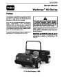


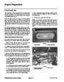
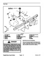


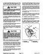
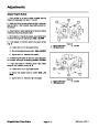

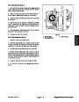
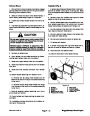
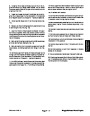
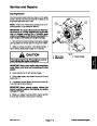


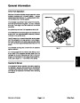
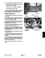


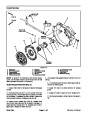
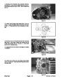


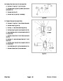
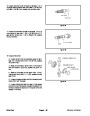


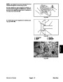


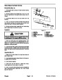


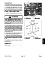
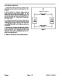


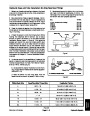
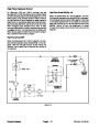


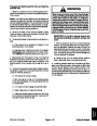
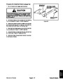

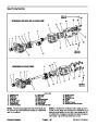

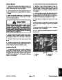


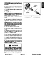
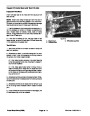


Engine Removal (Fig. 5)
Park vehicle on a level surface and engage parking
brake. Stop the engine and remove key from ignition
switch. Allow engine to cool.
1.
2
3
1
2.
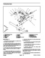
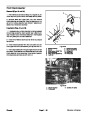
bed is raised, place safety support on lift cylinder.
Raise or remove the bed or other attachment(s). If
3.
cables at the battery.
Disconnect negative (--) and then positive (+) battery
5
2
4
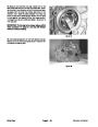
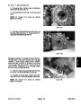
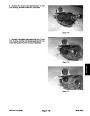
4.
harness (item 41) from starter solenoid stud on engine.
Disconnect positive cable (item 37) and fusible link
6
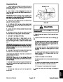
5.
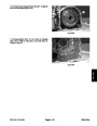
haust System Removal in this section).
Remove the muffler and exhaust manifold (see Ex-
6.
end of fuel hose to prevent contamination and fuel spill-
age.Positiondisconnected fuelhoseaway fromengine.
Disconnectfuelhosefromfuelpumponengine.Plug
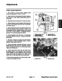
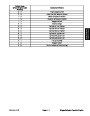
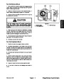
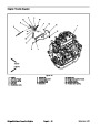
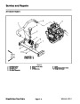
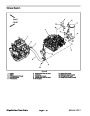
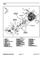
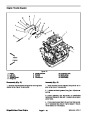
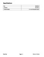
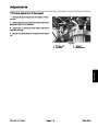
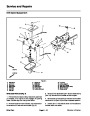
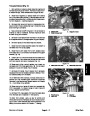
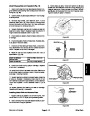
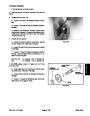
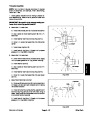
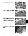
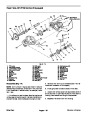
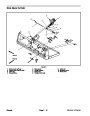
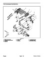
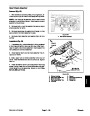
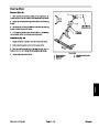
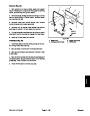
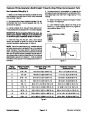
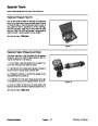
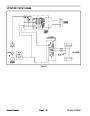
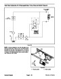
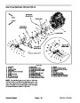
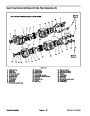
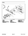
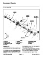
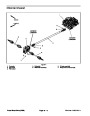
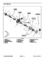
Figure 6
1.
2.
3.
Hydraulic pump
Flange nut (2 used)
Engine mount
4.
5.
6.
Pump drive belt
Carriage screw
Flange head screw
7.
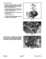
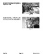
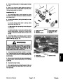
attach to engine and engine accessories.
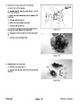
Label and disconnect wire harness connectors that
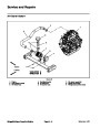
8.
gine mount (Fig. 6).Rotatepump towardengine toallow
drive belt to be removed from pump and engine pulleys.
Loosen fasteners that secure hydraulic pump to en-
2
1
3
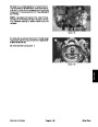
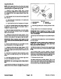
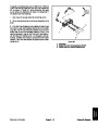
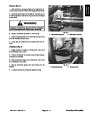
9.
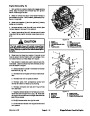
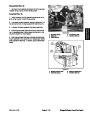
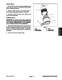
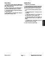
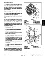
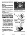
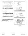
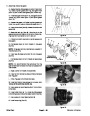
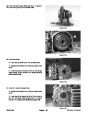
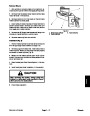
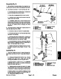
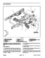
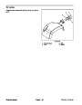
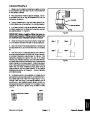
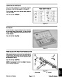
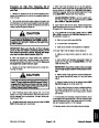
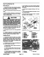
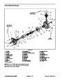
Disconnect accelerator cable ball joint (item 11) from
4
throttle lever on engine. Loosen jam nuts on cable and
remove cable from throttle bracket. Position accelerator
cable away from engine (Fig. 7).
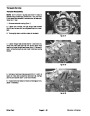
10.Disconnect
choke cable (item 33) from choke lever
on engine. Remove choke cable from bracket (Fig. 7).
11.
Remove all clamps and cable ties that attach wire
harness, hoses and cables to the engine.
12.Put
ing during engine removal.
blocking under transaxle to prevent it from mov-
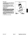
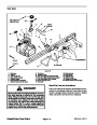
Figure 7
1.
2.
Accelerator cable
Ball joint
3.
4.
Jam nuts
Choke cable
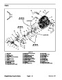
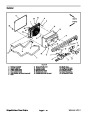
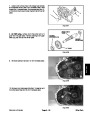
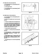
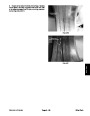
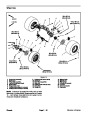
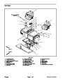
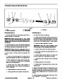
13.Loosen
and remove four (4) flange nuts (item 34)
and flange head screws (item 36) that secure engine to
engine mount.
17.If
(item 3) from stub shaft on flywheel side of engine. Lo-
cate and retrieve woodruff key (item 4).
necessary, remove hydraulic pump drive pulley
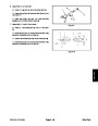
14.Remove
six(6)capscrews (item 19)andtwo (2)har-
ness brackets (item 46) that secure clutch bell housing
to clutch adapter on engine.
18.If
sary,seeClutch Service inthe Service and Repairs sec-
tion of Chapter 6 -- Drive Train.
pressure plate and clutch disc removal is neces-
15.Use
lift or hoist to remove engine from chassis. One
person should operate hoist and a second person
should help guide engine out of chassis. Move engine
forward before lifting to disengage transaxle input shaft
from clutch.
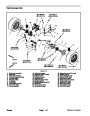
Flywheel and Pilot Bearing Inspection
1.
streaking orseizure andreplace ifnecessary.Check fly-
wheel runout and replace if runout exceeds 0.005 in.
Inspect flywheel (item 20) surface for stepped wear,
16.Note
location and retrieve two (2) dowel pins (item
(0.13
mm).
48)
from bell housing.
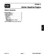
Workman HD
Kohler Gasoline Engine
Page 5 -- 11
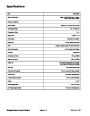
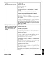
| Categories | Lawn Mower Manual, Sprinkler and Irrigation Manuals, Toro Sprinkler and Irrigation Manuals |
|---|---|
| Tags | Toro 09173SL |
| Download File |
|
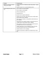
| Document Type | Service Manual |
| Language | English |
| Product Brand | Toro. Customer Service Representatives are available by phone:
Monday - Friday 7:30 a.m. to 9:00 p.m. (CDT) - Saturday 8:00 a.m. to 8:00 p.m. (CDT) - Sunday 10:00 a.m. to 8:00 p.m. (CDT)
Canada 1-888-225-4886 USA 1-888-384-9939, Lawn Mower |
| Document File Type | |
| Publisher | toro.com |
| Wikipedia's Page | Toro Company |
| Copyright | Attribution Non-commercial |
(0 votes, average: 0 out of 5)