


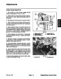
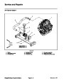
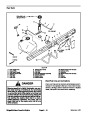
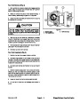


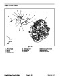

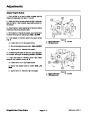

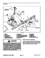
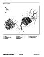
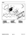
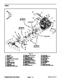
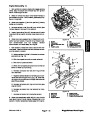

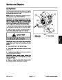


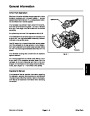
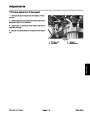
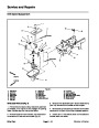
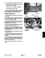


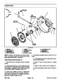
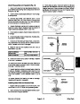
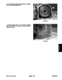


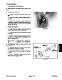
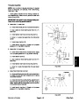


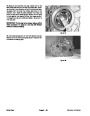
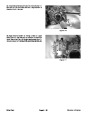
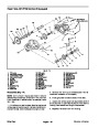
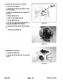


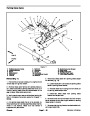
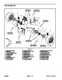


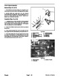
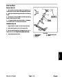


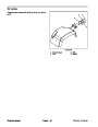

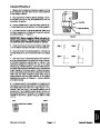
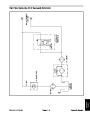

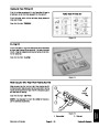


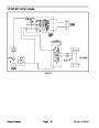
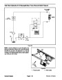

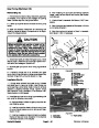

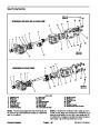
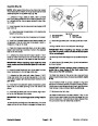


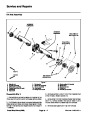
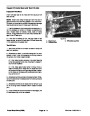


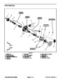
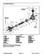


Removal (Fig. 25)
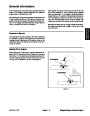
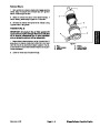
Parkvehicleonalevelsurface,raiseandsupportbed
(if installed), shut engine off and engage parking brake.
Remove key from the ignition switch.
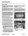
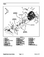
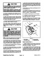
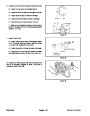
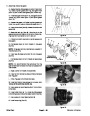
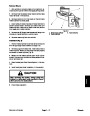
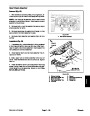
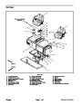
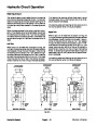
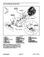
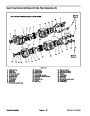
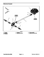
Installation (Fig. 25)
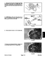
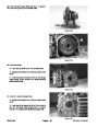
1.
1. If fittings were removed from gear pump, lubricate
and place new O--rings onto fittings. Install fittings into
pump openings using marks made during the removal
process to properly orientate fittings. Tighten fittings
(see Hydraulic Fitting Installation in the General Infor-
mation section of this chapter).
2.
Installing Hydraulic System Components at the begin-
ning of this chapter section.
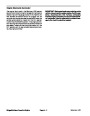
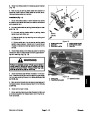
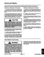
Read the General Precautions for Removing and
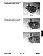
2.
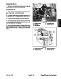
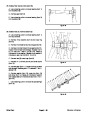
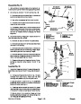
Install square key to the pump shaft. Apply antiseize
lubricant to gear pump shaft.
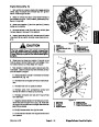
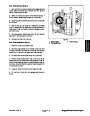
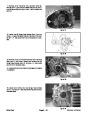
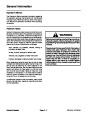
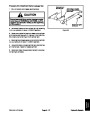
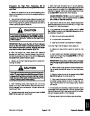
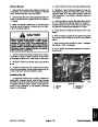
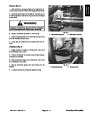
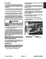
CAUTION
3.
Alignpumpshafttopumphub.Slidepumptowardthe
rear of machine until pump flange holes align with holes
in mount. Take care to not damage the pump coupling.
Before performing any service or repair on hy-
draulic system components, relieve system
pressure to avoid injury from pressurized hy-
draulic oil. Stop the engine, remove key from the
ignition switch, rotate the steering wheel in both
directions, lower the bed onto the bed support
and operate other hydraulic accessories.
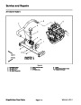
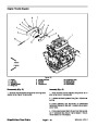
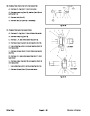
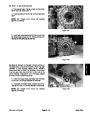
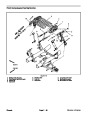
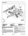
4. Install four (4) flange head screws and flange nuts to
secure pump to mount. Do not fully tighten fasteners.
5.
Position pump hub on pumpshaft sothatrubber cou-
plings are not distorted.
6.
cure hub to the pump shaft.
Tightenbothscrews (item23)onthe pumphub tose-
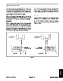
NOTE: If vehicle is equipped with High Flow Hydraulics
Kit, label hydraulic hoses for assembly purposes.
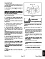
7.
that no deflection of coupler components exists. Fully
tighten fasteners to secure pump to mount.
Allow coupler assembly to locate pump making sure
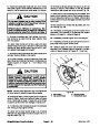
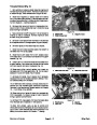
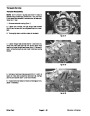
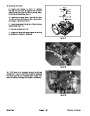
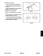
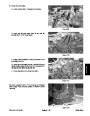
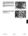
3.
Thoroughly clean junction of hydraulic hoses and
gear pump fittings. Disconnect hydraulic hoses from
gear pump. Install caps or plugs in hoses and pump fit-
tings to prevent contamination and leakage of hydraulic
oil.
8.
Remove plugs from hydraulic hoses and pump fit-
tings. Connect hydraulic hoses to gear pump (see Hy-
draulic Hose and Tube Installation in the General
Information section of this chapter).
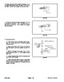
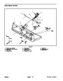
4.
allow pump hub removal from the gear pump shaft.
Loosen two (2) screws (item 23) on the pump hub to
IMPORTANT: The hydraulic system used on ve-
hicles with the High Flow Hydraulics Kit use two (2)
separate hydraulic reservoirs and hydraulic fluid
type. Make sure to use correct oil when adding hy-
draulic oil to the hydraulic system.
5.
removal.
Support gear pump to prevent it from falling during
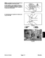
6.
that secure pump to mount.
Remove four (4) flange nuts and flange head screws
7.
gear pump from vehicle. Locate and retrieve square key
from the pump shaft.
Slide gear pump shaft out of pump hub and remove
9. Check oil level in the reservoir(s) and add correct oil
if necessary.
10.Start
the engine and operate at idle speed until air is
8.
If hydraulic fittings are to be removed from gear
out of hydraulic system.
pump, mark fitting orientation to allow correct assembly.
Remove fittings from pump and discard O--rings.
11.
Add correct oil if necessary.
Stop the engine and recheck oil level in reservoir(s).
Workman HD Series
Page 9 -- 33
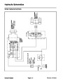
Hydraulic System
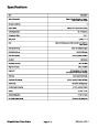
| Categories | Lawn Mower Manual, Sprinkler and Irrigation Manuals, Toro Sprinkler and Irrigation Manuals |
|---|---|
| Tags | Toro 09173SL |
| Download File |
|
| Document Type | Service Manual |
| Language | English |
| Product Brand | Toro. Customer Service Representatives are available by phone:
Monday - Friday 7:30 a.m. to 9:00 p.m. (CDT) - Saturday 8:00 a.m. to 8:00 p.m. (CDT) - Sunday 10:00 a.m. to 8:00 p.m. (CDT)
Canada 1-888-225-4886 USA 1-888-384-9939, Lawn Mower |
| Document File Type | |
| Publisher | toro.com |
| Wikipedia's Page | Toro Company |
| Copyright | Attribution Non-commercial |
(0 votes, average: 0 out of 5)