


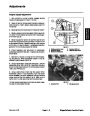
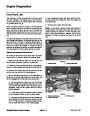
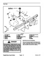


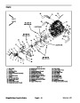
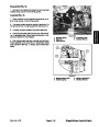
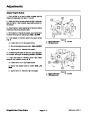
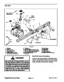
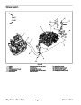
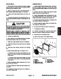
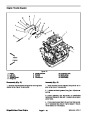
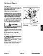


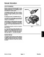
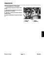
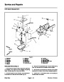


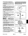
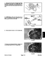


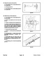

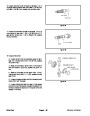
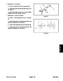


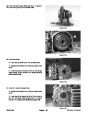
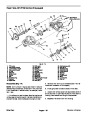


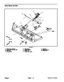
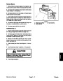
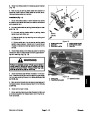
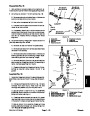


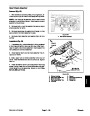


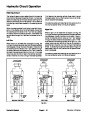

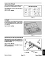


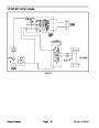
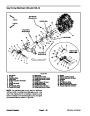

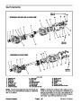
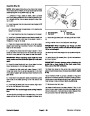
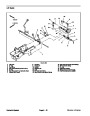


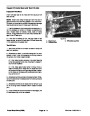

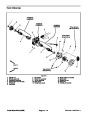


Removal (Fig. 8)
Park vehicle on a level surface, shut engine off, re-
move key from ignition switch and apply parking brake.
Block rear wheels to prevent the vehicle from moving
unexpectedly.
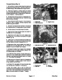
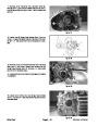
2. Secure differential to the frame with four (4) flange
head screws (item 4).
1.
3. Install and tighten inner two (2) flange head screws
and flange nuts that secure control arm tower to upper
control arm (Fig. 9).
2.
moving the drain plug. Install drain plug after draining.
Drain differential oil into a suitable container by re-
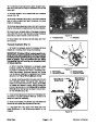
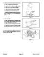
4. Apply antiseize lubricant to input shaft of differential.
Slide driveshaft yoke onto differential input shaft.
3.
4.
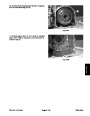
Unplug wire harness connector from differential.
Remove both CV axle assemblies from the differen-
5. Secure driveshaft yoke to the differential with cap
screw andflatwasher (seeDifferentialDriveshaft Instal-
lation in this section).
tial (see CV Axle Assembly Removal in this section).
6.
Assembly Installation in this section).
Install both CV axles to the differential (see CV Axle
5.
Remove cap screw and flat washer that secure dri-
veshaft yoke to the differential input shaft. Separate dif-
ferential driveshaft yoke from the differential input shaft
(see Differential Driveshaft Removal in this section).
7. Connect wire harness connector to differential.
8.
Makesuredifferentialdrain plugis installed properly.
Fill differential with oil.
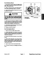
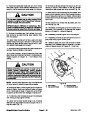
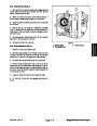
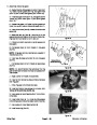
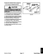
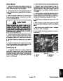
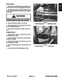
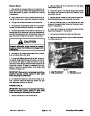
CAUTION
4
Support differential during removal to prevent
personal injury from falling and damage to the
differential.
2
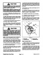
6.
Remove four (4) flange head screws (item 4) that se-
1
cure the differential to the frame.
7.
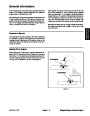
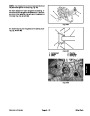
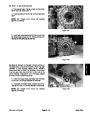
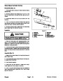
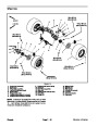
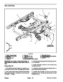
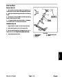
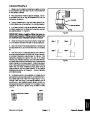
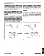
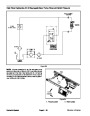
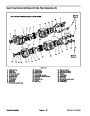
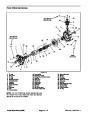
On right side (passenger side) of vehicle, remove in-
ner two (2) flange head screws and flange nuts that se-
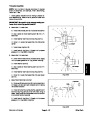
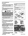
cure control arm tower to upper control arm (Fig. 9).
Removal of these two (2) fasteners allows clearance for
differential removal. To prevent unexpected front sus-
pension movement, do not loosen outer flange head
screws and flange nuts.
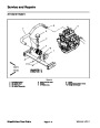
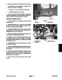
3
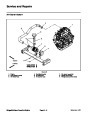
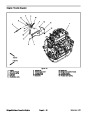
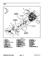
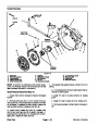
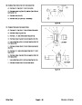
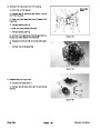
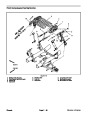
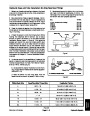
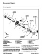
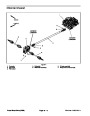
Figure 9
1.
2.
Upper RH control arm
Inner screw and nut
3.
4.
Differential
Outer screw and nut
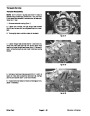
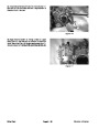
IMPORTANT: Make sure to not damage brake lines,
electrical harness, control cables or other parts
while removing the differential.
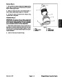
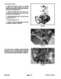
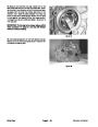
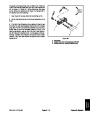
8.
hicle. Remove differential assembly toward the right
side (passenger side) of the vehicle.
Tip differential toward left side (driver side) of ve-
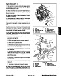
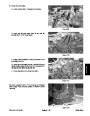
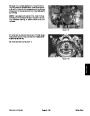
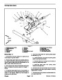
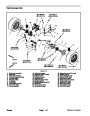
Installation (Fig. 8)
IMPORTANT: Make sure to not damage brake lines,
electrical harness, control cables or other parts
while installing the differential to the vehicle.
1.
Position differential to the vehicle frame.
Workman HDX/HDX--D
Page 10 -- 13
Front Wheel Drive (4WD)
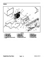
| Categories | Lawn Mower Manual, Sprinkler and Irrigation Manuals, Toro Sprinkler and Irrigation Manuals |
|---|---|
| Tags | Toro 09173SL |
| Download File |
|
| Document Type | Service Manual |
| Language | English |
| Product Brand | Toro. Customer Service Representatives are available by phone:
Monday - Friday 7:30 a.m. to 9:00 p.m. (CDT) - Saturday 8:00 a.m. to 8:00 p.m. (CDT) - Sunday 10:00 a.m. to 8:00 p.m. (CDT)
Canada 1-888-225-4886 USA 1-888-384-9939, Lawn Mower |
| Document File Type | |
| Publisher | toro.com |
| Wikipedia's Page | Toro Company |
| Copyright | Attribution Non-commercial |
(0 votes, average: 0 out of 5)