
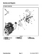
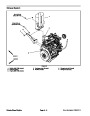
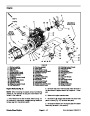


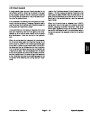
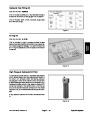
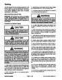


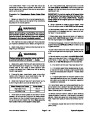
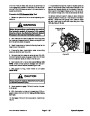
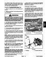
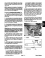


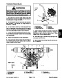
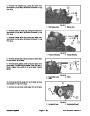
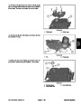
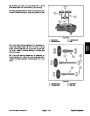


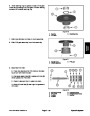
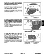
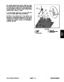
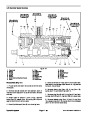


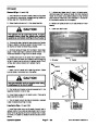
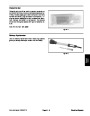
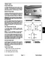
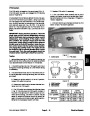
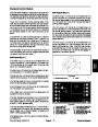
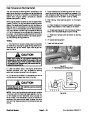
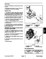
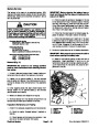
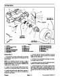
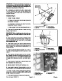
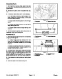
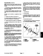


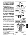
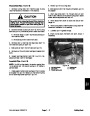


High Temperature Warning Switch
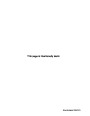
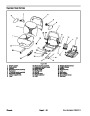
The high temperature warning switch is attached to the
water pump housing on the engine and has a yellow wire
attached to it (Fig. 27). This switch is normally open and
closes when engine coolant temperature reaches
approximately 220oF (105oC).
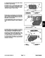
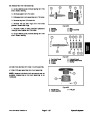
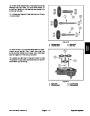
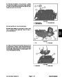
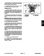
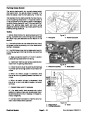
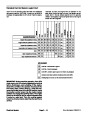
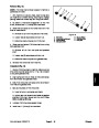
4. Check resistance of the warning switch with a multi-
meter (ohms setting) as the temperature increases. The
high temperature warning switch is normally open and
should close from 216o to 226oF (102o to 108oC).
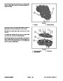
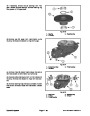
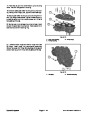
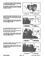
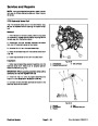
5. After testing, install warning switch to the engine
housing.
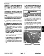
When engine coolant temperature rises to approximate-
ly 220oF (105oC), the high temperature warning switch
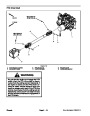
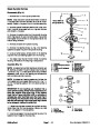
A. Clean threads of housing and switch thoroughly.
Apply thread sealant to the threads of the switch.
closes. The closed switch causes the High Temperature
Warning Light on the console to illuminate and also pro-
vides an input to the Standard Control Module (SCM).
This input causes the SCM high temperature warning
LED to illuminate and the cutting deck (or implement) to
shut down. The temperature warning switch and circuit
wiring should be tested as a SCM input before perform-
ing the following testing procedure.
B. Thread warning switch into the housing. Torque
switch from 16 to 20 ft–lb (21.7 to 27.1 N–m).
C. Reconnect harness wire connector to warning
switch.
6.
7.
Fill engine cooling system.
Lower and secure hood.
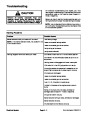
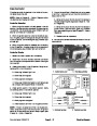
Testing
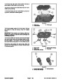
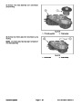
1.
Park machine on a level surface, lower cutting deck
(or implement), stop engine, apply parking brake and re-
move key from ignition switch. Open hood to gain ac-
cess to engine.
1
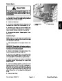
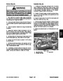
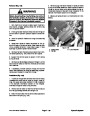
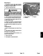
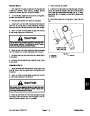
CAUTION
Make sure engine is cool before removing the
temperature warning switch from engine. Do not
open radiator cap or drain coolant if the radiator
or engine is hot. Pressurized, hot coolant can es-
cape and cause burns.
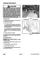
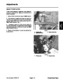
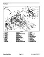
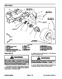
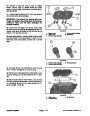
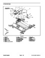
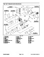
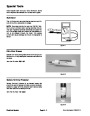
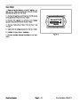
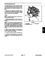
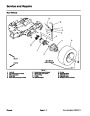
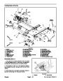
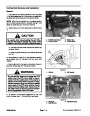
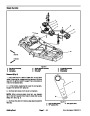
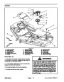
Figure 27
1.
High temperature warning switch
2.
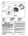
Lower the coolant level in the engine, remove wire
harness connector from high temperature warning
switch and remove the switch from the engine.
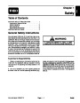
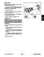
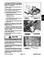
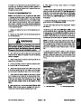
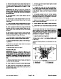
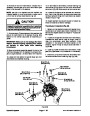
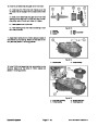
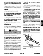
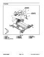
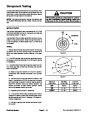
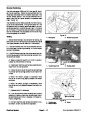
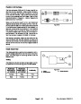
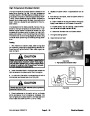
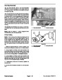
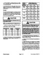
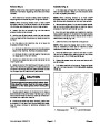
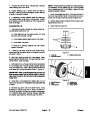
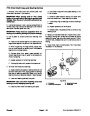
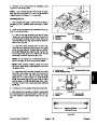
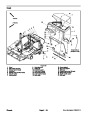
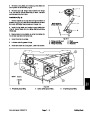
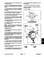
3.
thermometer and slowly heat the oil (Fig. 28).
Put the end of the switch in a container of oil with a
CAUTION
Handle the hot oil with extreme care to prevent
personal injury or fire.
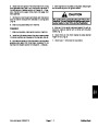
NOTE: Prior to taking resistance readings with a digital
multimeter, short the meter test leads together. The me-
ter will display a small resistance value (usually 0.5
ohms or less). This resistance is due to the internal re-
sistance of the meter and test leads. Subtract this value
from from the measured value of the component you are
testing.
Figure 28
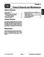
Electrical System
Page 5 – 22
Groundsmaster 7200/7210
| Categories | Lawn Mower Manual, Sprinkler and Irrigation Manuals, Toro Sprinkler and Irrigation Manuals |
|---|---|
| Tags | Toro Groundsmaster 7200, Toro Groundsmaster 7210 |
| Download File |
|
| Document Type | Service Manual |
| Language | English |
| Product Brand | Toro. Customer Service Representatives are available by phone:
Monday - Friday 7:30 a.m. to 9:00 p.m. (CDT) - Saturday 8:00 a.m. to 8:00 p.m. (CDT) - Sunday 10:00 a.m. to 8:00 p.m. (CDT)
Canada 1-888-225-4886 USA 1-888-384-9939, Lawn Mower |
| Document File Type | |
| Publisher | toro.com |
| Wikipedia's Page | Toro Company |
| Copyright | Attribution Non-commercial |
(0 votes, average: 0 out of 5)
My mower is a TORO 7210.
Start fuse defection. Why ?