


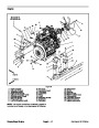
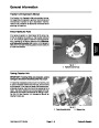


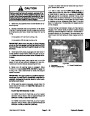


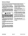


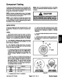


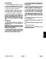


Component Testing
For accurate resistance and/or continuity checks, elec-
trically disconnect the component being tested from the
circuit (e.g. unplug the ignition switch connector before
doing a continuity check of the switch).
NOTE: See the Kubota Workshop Manual: 05 Series
Engine for additional electrical component repair in-
formation.
NOTE: Electrical troubleshooting of any 12 volt power
connectioncanbeperformedthroughvoltagedroptests
without disconnecting the component.
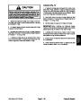
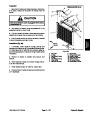
CAUTION
When testing electrical components for continu-
ity with a multimeter (ohms setting), make sure
that power to the circuit has been disconnected.
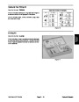
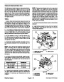
NOTE: Use the Diagnostic Display (see Special Tools
in this chapter) to test Electronic Control Module inputs
and outputs before further troubleshooting of an electri-
cal problem on your Reelmaster.
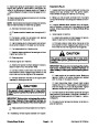
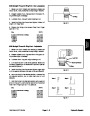
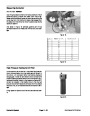
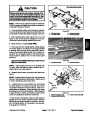
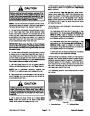
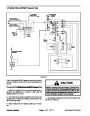
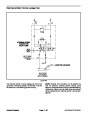
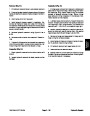
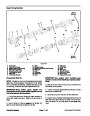
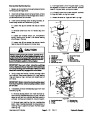
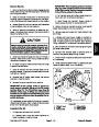
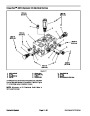
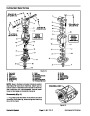
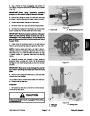
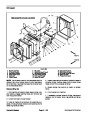
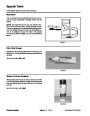
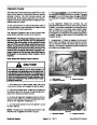
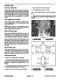
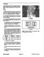
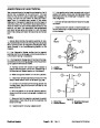
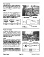
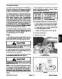
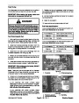
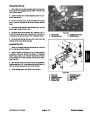
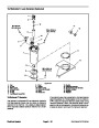
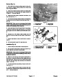
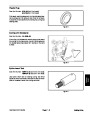
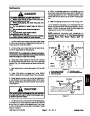
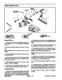
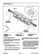
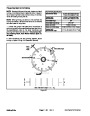
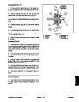
Ignition Switch
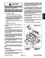
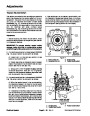
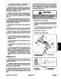
The ignition (key) switch has three positions (OFF, RUN
and START). The switch is mounted on the control con-
sole.
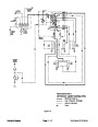
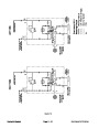
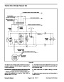
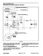
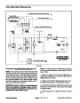
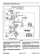
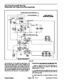
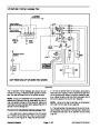
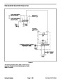
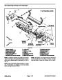
D. If ignition switch tests correctly and circuit prob-
lemstillexists,checkwireharness(seeWiringSche-
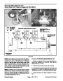
matic and Circuit Drawings in Chapter 9 -- Electrical
Diagrams).
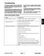
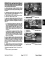
Testing
E. Connect harness electrical connector to the igni-
tion switch.
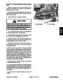
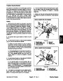
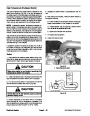
1.
Before disconnecting the ignition switch for testing,
the switch and its circuit wiring should be tested as an
ECM input with the Diagnostic Display (see Diagnostic
Display in the Troubleshooting section of this chapter).
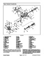
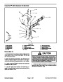
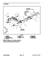
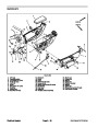
F. Install control arm cover to machine (see Control
Arm Assembly in the Service and Repairs section of
this chapter).
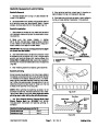
2.
If the Diagnostic Display verifies that ignition switch
and circuit wiring are functioning correctly, no further
switch testing is necessary.
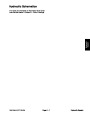
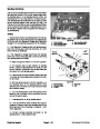
OFF
45
°
RUN
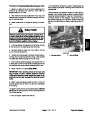
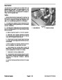
3.
switch and circuit wiring are not functioning correctly,
If the Diagnostic Display determines that ignition
test ignition switch as follows:
45 °
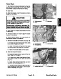
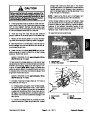
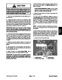
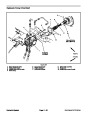
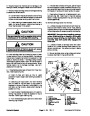
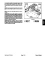
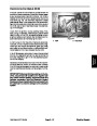
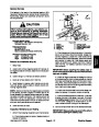
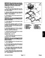
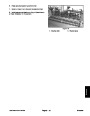
A. Removeoutsidecontrolarmcovertogainaccess
to ignition switch (see Control Arm Disassembly in
the Service and Repairs section ofthis chapter). Dis-
connect harness electrical connector from the
switch.
START
Figure 23
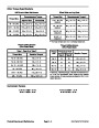
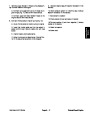
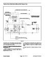
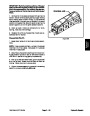
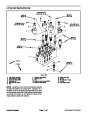
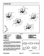
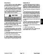
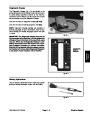
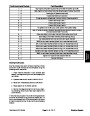
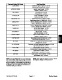
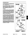
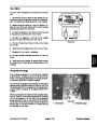
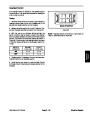
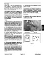
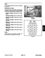
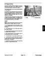
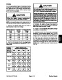
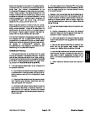
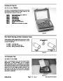
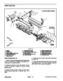
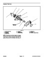
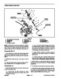
B. With the use of a multimeter (ohms setting), the
switch functions maybetestedtodeterminewhether
continuity exists between the various terminals for
each switch position. The ignition switch terminals
are marked as shown in Figure 24. The circuitry of
this switch is shown in the chart below. Verify conti-
nuity between switch terminals.
A
B
I
Y
X
A
S
S
POSITION
OFF
CIRCUIT
B
Y
NONE
X
I
RUN
B + I + A, X + Y
B + I + S
SERIAL NUMBER
BELOW 310000000
SERIAL NUMBER
ABOVE 310000000
START
Figure 24
C. Replace ignition switch if necessary.
Reelmaster 5010 Series
Page 5 -- 23 Rev. B
Electrical System
| Categories | Lawn Mower Manual, Sprinkler and Irrigation Manuals, Toro Sprinkler and Irrigation Manuals |
|---|---|
| Tags | Toro 5210, Toro 5410, Toro 5510, Toro 5610 |
| Download File |
|
| Document Type | Catalog, Service Manual |
| Language | English |
| Product Brand | Toro. Customer Service Representatives are available by phone:
Monday - Friday 7:30 a.m. to 9:00 p.m. (CDT) - Saturday 8:00 a.m. to 8:00 p.m. (CDT) - Sunday 10:00 a.m. to 8:00 p.m. (CDT)
Canada 1-888-225-4886 USA 1-888-384-9939, Lawn Mower |
| Document File Type | |
| Publisher | toro.com |
| Wikipedia's Page | Toro Company |
| Copyright | Attribution Non-commercial |
(1 votes, average: 4 out of 4)
Lawn and Garden readers have rated Toro 06148SL Rev B Reelmaster 5210 5410 5510 5610 Service Manual 4.0 out of 4.0 based on 1 product reviews. i hope is going to work