

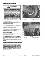


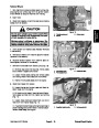


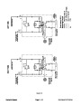
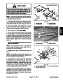
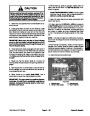
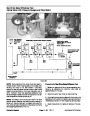
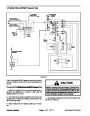


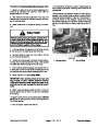


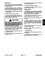
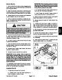

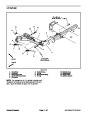


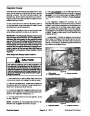


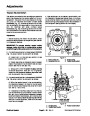
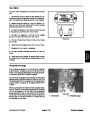
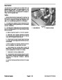


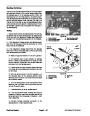
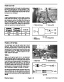
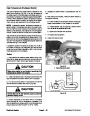
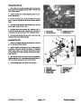


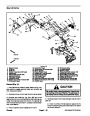


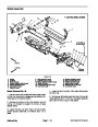


Removal (Fig. 15)
Park machine on a level surface, lower cutting units,
stop engine, engage parking brake and remove key
from the ignition switch.
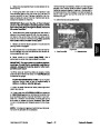
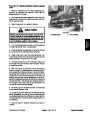
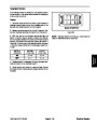
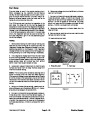
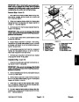
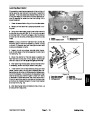
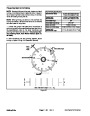
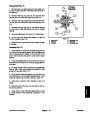
3. Align lift cylinder to lift arm mounting slot (Fig. 16).
Slide cylinder pin (Fig. 16 item 5) with retaining ring (Fig.
1.
16
item 3) and thrust washer (Fig. 16 item 4) through the
lift cylinder and lift arm. Install second thrust washer on
pin and secure with second retaining ring.
2.
3.
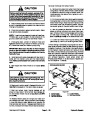
Removecuttingunitfromfrontliftarmtoberemoved.
Remove one retaining ring (Fig.16 item3) andthrust
4.
5.
if necessary (see Up Limit Switch in Components sec-
tion of Chapter 5 -- Electrical System).
Mount cutting unit to lift arm.
Check operation of lift arm up limit switch and adjust
washer(Fig.16item4)fromthecylinderpin(Fig.16item
5)
fromtheliftcylinderandliftarm.Locateandretrievesec-
ond thrust washer.
that secures lift cylinder to lift arm. Pull cylinder pin
6. Lubricate lift arm grease fittings.
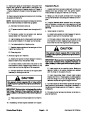
4.
5.
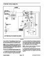
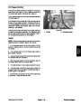
sembly from lift arm. Locate and retrieve two (2) thrust
washers (item 18).
Pivot lift cylinder rod end away from lift arm.
Remove lynch pin (item 17) and slide pivot yoke as-
4
4
5
3
3
2
6.
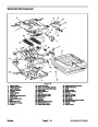
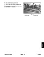
Remove fasteners that secure bridge plate to ma-
chine.
7.
8.
ordamage.Ifnecessary,replacebushings(Figs.17and
18).
Slide front lift arm from lift arm pivot shaft.
Inspect bushings in lift arm and pivot yoke for wear
1
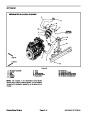
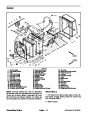
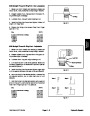
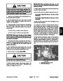
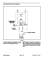
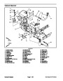
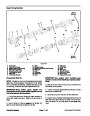
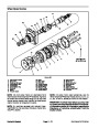
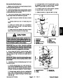
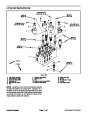
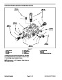
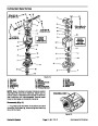
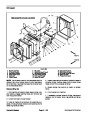
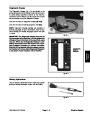
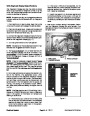
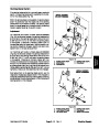
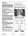
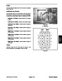
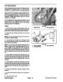
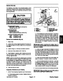
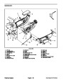
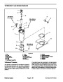
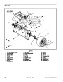
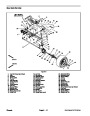
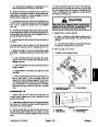
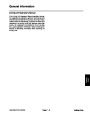
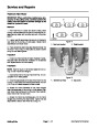
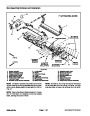
Figure 16
1.
2.
3.
Lift arm (#5 shown)
Lift cylinder
Retaining ring
4.
5.
Thrust washer
Cylinder pin
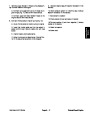
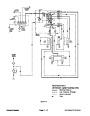
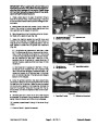
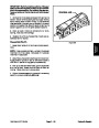
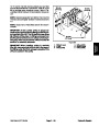
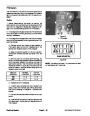
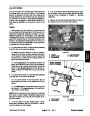
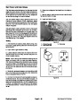
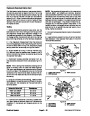
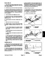
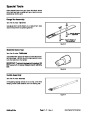
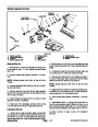
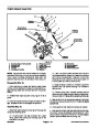
A. Use bushing removal tool to extract bushings
from the lift arm or pivot yoke. Take care to not dam-
age the bore.
B. Clean the inside of the bore to remove any dirt or
foreign material.
3
1
2
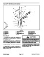
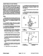
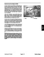
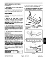
C. Apply grease to the inside and outside of the new
bushings.
D. Use an arbor press to install the bushings into lift
arm or pivot yoke. Lift arm bushings should be
pressed until bushing flange is against lift arm bore.
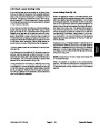
The upper pivot yoke bushing should be pressed ful-
ly to the shoulder in the pivot yoke bore. The lower
pivot yoke bushing should be flush with the yoke
tube.
2
3
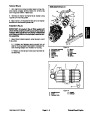
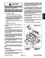
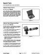
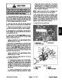
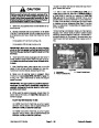
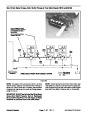
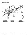
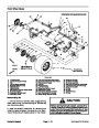
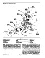
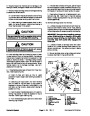
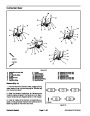
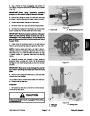
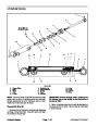
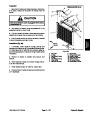
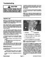
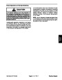
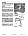
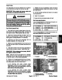
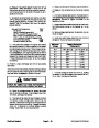
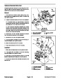
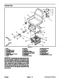
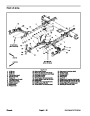
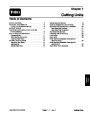
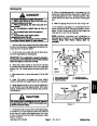
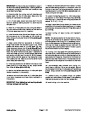
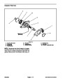
Figure 17
3.
1.
2.
Lift arm (#1 shown)
Lift arm bushing
Pivot yoke bushing
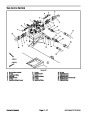
Installation (Fig. 15)
2
1.
Slide front lift arm onto pivot shaft. Secure lift arm
1
with bridge plate. Torque flange screw(s) (item 12) that
secure bridge plate to pivot shaft(s) from 67 to 83 ft--lb
3
(91
to 112 N--m).
2.
Positionthrustwasher(item18)ontopivotyokeshaft
and then slide pivot yoke into lift arm bushings. Place
second thrust washer on pivot yoke shaft and secure
with lynch pin (item 17).
4
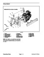
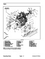
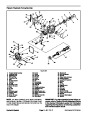
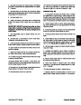
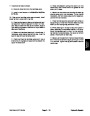
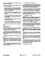
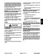
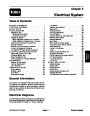
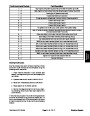
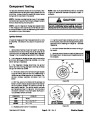
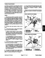
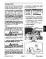
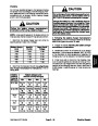
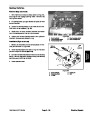
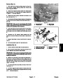
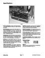
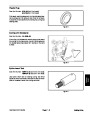
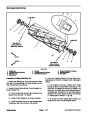
Figure 18
1.
2.
Pivot yoke
Upper bushing
3.
4.
Pivot yoke shoulder
Lower bushing
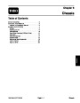
Reelmaster 5010 Series
Page 6 -- 21
Chassis
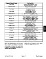
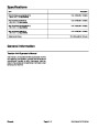
| Categories | Lawn Mower Manual, Sprinkler and Irrigation Manuals, Toro Sprinkler and Irrigation Manuals |
|---|---|
| Tags | Toro 5210, Toro 5410, Toro 5510, Toro 5610 |
| Download File |
|
| Document Type | Catalog, Service Manual |
| Language | English |
| Product Brand | Toro. Customer Service Representatives are available by phone:
Monday - Friday 7:30 a.m. to 9:00 p.m. (CDT) - Saturday 8:00 a.m. to 8:00 p.m. (CDT) - Sunday 10:00 a.m. to 8:00 p.m. (CDT)
Canada 1-888-225-4886 USA 1-888-384-9939, Lawn Mower |
| Document File Type | |
| Publisher | toro.com |
| Wikipedia's Page | Toro Company |
| Copyright | Attribution Non-commercial |
(1 votes, average: 4 out of 4)
Lawn and Garden readers have rated Toro 06148SL Rev B Reelmaster 5210 5410 5510 5610 Service Manual 4.0 out of 4.0 based on 1 product reviews. i hope is going to work