
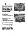


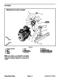
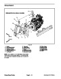
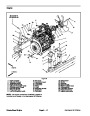
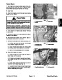
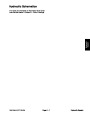


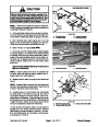
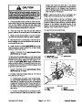
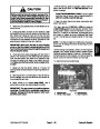
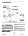
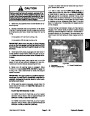
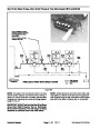


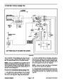
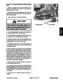
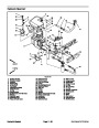
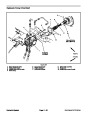


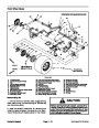

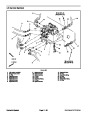
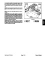
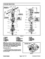
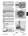


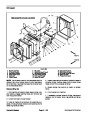

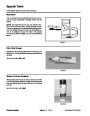
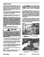


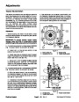
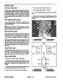


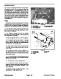
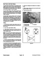
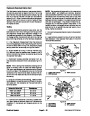
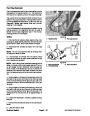
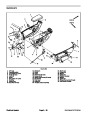
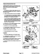
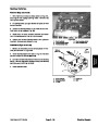


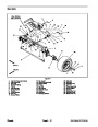
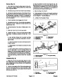
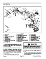
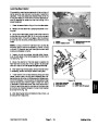
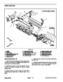
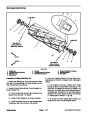


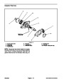


Main Power and Glow Relays
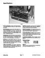
The Reelmaster electrical system includes two identical
relays for current control. The main power and glow re-
laysareattachedtoaframebracketunderthehoodnext
to the hydraulic pump drive shaft (Fig. 42). Relays can
be identified by a tag on the wire harness.
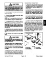
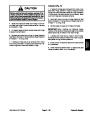
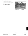
6. Disconnect voltage and test leads from the relay ter-
minals.
7.
Secure relay to machine and connect machine wire
harness connector to relay.
8.
Lower and secure hood.
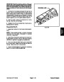
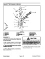
The main power relay is used to provide current to the
Electronic Control Module (ECM), headlights, power
point and optional electric equipment. When the ignition
switch is in the RUN or START position, the main power
relay is energized.
1
2
The glow relay is used to provide current to the engine
glow plugs when energized by the ECM. The ECM con-
trols and monitors the operation of the glow relay. The
glow relay and its circuit wiring should be tested as an
ECM output with the Diagnostic Display before discon-
necting and testing the relay (see Special Tools and
Troubleshooting in this chapter).
3
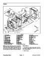
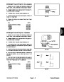
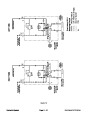
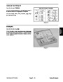
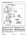
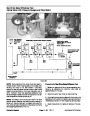
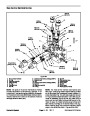
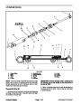
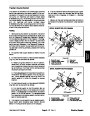
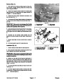
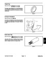
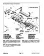
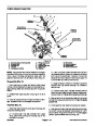
Testing
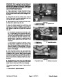
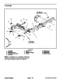
Figure 42
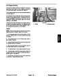
1.
stop engine, apply parking brake and remove key from
ignition switch.
Park machine on a level surface, lower cutting units,
1. Pump drive shaft
2. Main power relay
3.
Glow relay
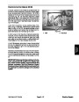
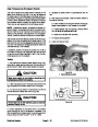
2.
3.
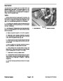
ness connector from the relay. Remove relay from ma-
chine for easier testing.
Open hood to gain access to relay.
Locate relay and disconnect the machine wire har-
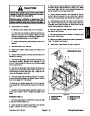
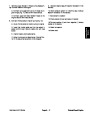
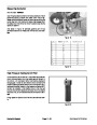
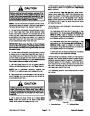
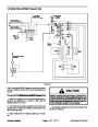
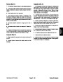
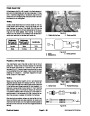
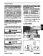
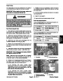
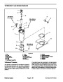
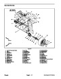
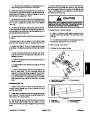
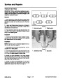
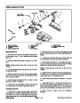
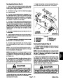
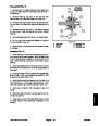
30
85
86
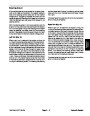
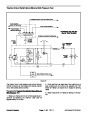
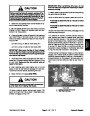
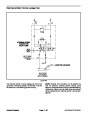
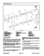
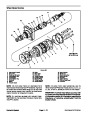
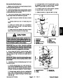
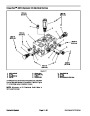
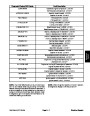
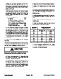
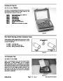
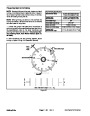
NOTE: Prior to taking small resistance readings with a
digital multimeter, short the meter test leads together.
The meter will display a small resistance value (usually
87
0.5
ohms or less). This resistance is due to the internal
resistance of the meter and test leads. Subtract this val-
ue from from the measured value of the component you
are testing.
86
85
87
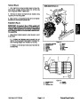
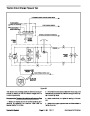
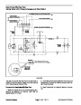
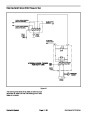
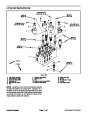
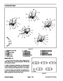
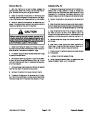
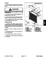
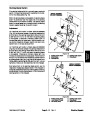
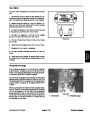
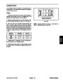
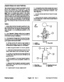
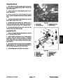
4.
Verify coil resistance between terminals 85 and 86
with a multimeter (ohms setting) (Fig. 43). Resistance
should be approximately 72 ohms.
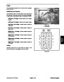
30
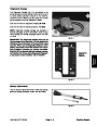
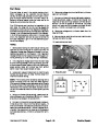
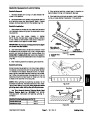
5.
Connectmultimeter (ohmssetting) leadstorelayter-
Figure 43
minals 30 and 87. Ground terminal 86 and apply +12
VDCtoterminal85.Therelayshouldhavecontinuitybe-
tween terminals 30 and 87 as +12 VDC is applied to ter-
minal 85. The relay should not have continuity between
terminals 30 and 87 as +12 VDC is removed from termi-
nal 85.
Electrical System
Page 5 -- 36
Reelmaster 5010 Series
| Categories | Lawn Mower Manual, Sprinkler and Irrigation Manuals, Toro Sprinkler and Irrigation Manuals |
|---|---|
| Tags | Toro 5210, Toro 5410, Toro 5510, Toro 5610 |
| Download File |
|
| Document Type | Catalog, Service Manual |
| Language | English |
| Product Brand | Toro. Customer Service Representatives are available by phone:
Monday - Friday 7:30 a.m. to 9:00 p.m. (CDT) - Saturday 8:00 a.m. to 8:00 p.m. (CDT) - Sunday 10:00 a.m. to 8:00 p.m. (CDT)
Canada 1-888-225-4886 USA 1-888-384-9939, Lawn Mower |
| Document File Type | |
| Publisher | toro.com |
| Wikipedia's Page | Toro Company |
| Copyright | Attribution Non-commercial |
(1 votes, average: 4 out of 4)
Lawn and Garden readers have rated Toro 06148SL Rev B Reelmaster 5210 5410 5510 5610 Service Manual 4.0 out of 4.0 based on 1 product reviews. i hope is going to work