


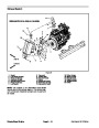


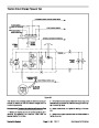
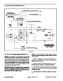
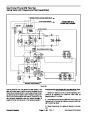


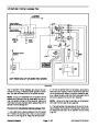


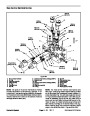
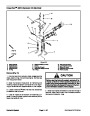
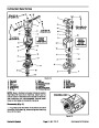
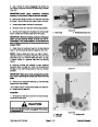


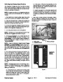


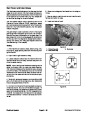
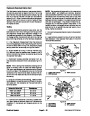


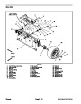


Lift Circuit: Raise Cutting Units
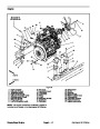
A four section gear pump is coupled to the piston (trac-
tion) pump. Gear pump section (P4) supplies hydraulic
flow to the lift control manifold and ultimately for the lift
cylinders. The gear pump takes its suction from the hy-
draulic reservoir. Lift circuit pressure is limited to 2000
PSI (138 bar) by a solenoid relief valve (SVRV) located
in the lift control manifold.
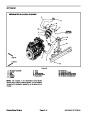
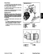
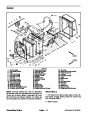
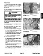
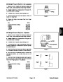
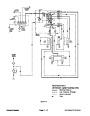
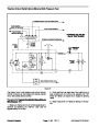
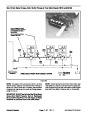
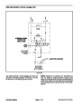
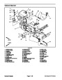
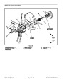
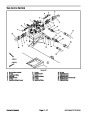
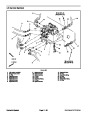
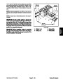
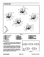
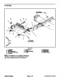
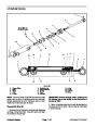
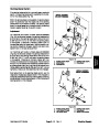
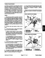
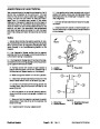
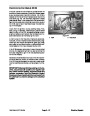
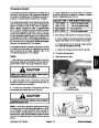
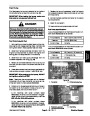
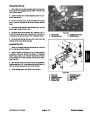
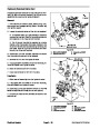
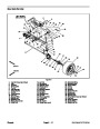
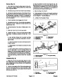
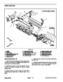
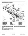
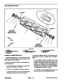
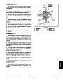
Raise Cutting Units (Fig. 11)
When the joystick is moved to the raise position, sole-
noid valve (SVRV)energizes alongwith solenoid valves
(SV1), (SV2) and (SV3). The energized solenoid valves
direct gear pump section P4 oil flow to the rod end of the
lift cylinders. Hydraulic pressure against the rod side of
the cylinders causes the shafts to retract, and raises the
cutting units. Fixed orifices in the lift control manifold
(C1L, C4L, C5L and C23L) control the lifting speed by
providing a restriction for the return flow from the lift cyl-
inders.
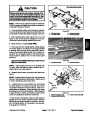
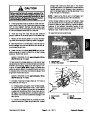
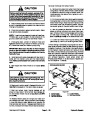
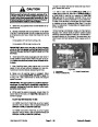
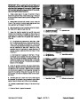
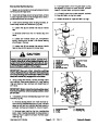
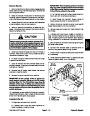
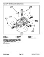
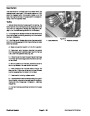
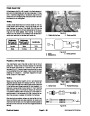
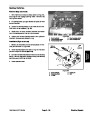
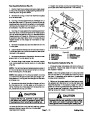
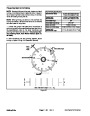
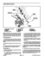
The lift control manifold includes four (4) electrically op-
erated solenoid valves. Valve (SVRV) is used to direct
gear pump flow to the lift cylinders when energized or
bypass pump flow back to the reservoir when de--ener-
gized. Valve (SV2) is used to direct oil flow to retract the
lift cylinders when energized or extend them when de--
energized. Valve (SV1) allows hydraulic flow to the front
lift cylinders when energized. Valve (SV3) allows hy-
draulic flow to the rear lift cylinders when energized.
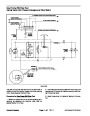
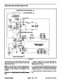
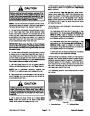
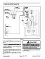
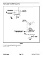
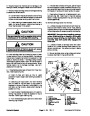
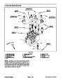
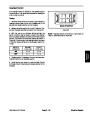
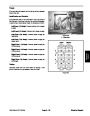
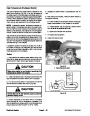
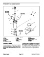
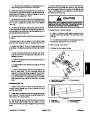
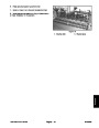
When the joystick is returned to the neutral (center)
position, the solenoid valves are de--energized and the
lift cylinders (and cutting units) are held in the raised
position. Piloted check valves in the lift control manifold
(CV1, CV4, CV5 and CV23) prevent the lift cylinders
(and cutting units) from dropping after they have been
raised.
Lift circuit pressure can be monitored at lift control man-
ifold port G4.
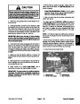
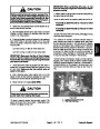
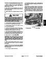
The Electronic Control Module (ECM) uses inputs from
various machine switches to determine when lift man-
ifold solenoid valves (SV1, SV2, SV3 and SVRV) are to
be energized. The ECM also provides a partial raise
position of the front outside cutting units.
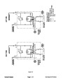
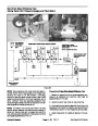
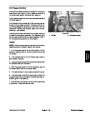
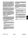
During conditions of not raising or lowering the cutting
units (joystick inthe neutral(center) position), allfour(4)
liftmanifoldsolenoid valves (SV1,SV2,SV3 andSVRV)
are de--energized. Hydraulic flow from gear pump sec-
tion(P4)by--passestheliftcylinders totheoil cooler and
then to the hydraulic reservoir.
Reelmaster 5010 Series
Page 4 -- 13
Hydraulic System
| Categories | Lawn Mower Manual, Sprinkler and Irrigation Manuals, Toro Sprinkler and Irrigation Manuals |
|---|---|
| Tags | Toro 5210, Toro 5410, Toro 5510, Toro 5610 |
| Download File |
|
| Document Type | Catalog, Service Manual |
| Language | English |
| Product Brand | Toro. Customer Service Representatives are available by phone:
Monday - Friday 7:30 a.m. to 9:00 p.m. (CDT) - Saturday 8:00 a.m. to 8:00 p.m. (CDT) - Sunday 10:00 a.m. to 8:00 p.m. (CDT)
Canada 1-888-225-4886 USA 1-888-384-9939, Lawn Mower |
| Document File Type | |
| Publisher | toro.com |
| Wikipedia's Page | Toro Company |
| Copyright | Attribution Non-commercial |
(1 votes, average: 4 out of 4)
Lawn and Garden readers have rated Toro 06148SL Rev B Reelmaster 5210 5410 5510 5610 Service Manual 4.0 out of 4.0 based on 1 product reviews. i hope is going to work